PWI000012
this document applies to :
This technique is commonly used when inspection reports are required in "Car-Line."
TRANSFORMATION MATRICES are used to achieve the desired effect.
This technique is commonly used when inspection reports are required in "Car-Line." The inspection report for the part is required in terms of the application (accuracy of the part measured as it actually sits in the finished vehicle) rather than in terms of production (measured using the part's own datum e.g. dieline).
Firstly you must know what the two orientations are, and how to change from one to the other.
TRANSFORM TO or FROM CAR-LINE to DIE-LINE MUST BE PROVIDED BY EITHER THE CUSTOMER OR CAD DEPARTMENT
There are four typical scenarios:
![]()
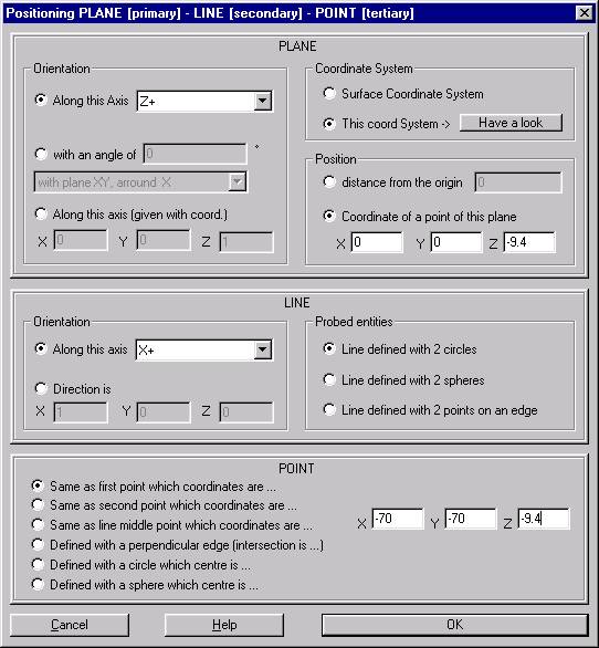
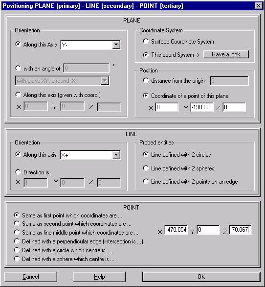
Fill the PLP box in DIE-LINE using Prismatic Positioning (after the CAD is on the screen).
The Plane, Line & Point information is entered in Die-Line using “This Coordinate System” & “Have a Look”
THEN
Select “This coordinate System”
Select “Have a look”
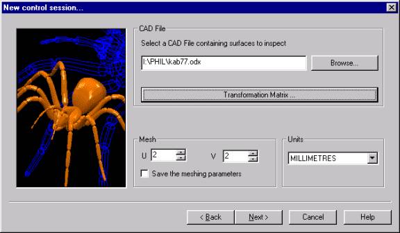
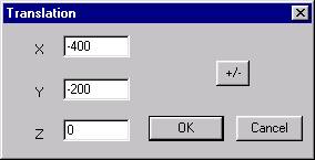
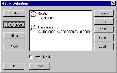
Matrix Definition :- fill in the Transform that takes you from DIE-LINE to CAR-LINE, using details provided by Customer or CAD department.
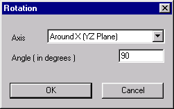
Build up the complete transformation

and select ‘OK.’

from details provided by the Customer or CAD department.
You carry out this transformation right at the beginning after browsing for the CAD, but before the file has been opened.
Build up the transformation
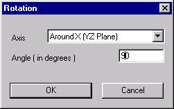
You will finish with the full transformation
Then continue to open the drawing, setting the PLP in CAR-LINE.
from details provided by the Customer or CAD department. (This is detailed in Case 3 above.)
This is to be done at the beginning after Browsing for the CAD and this puts the CAD in CAR-LINE.
At this point, the CAD drawing is now in CAR-LINE, and the PLP is still in DIE-LINE. This is now the same as Case 2 above.
At this point fill the PLP with DIE-LINE using Prismatic Positioning information from the DIE-LINE (after CAD is on the screen) and “This coord System” using the transformation matrix. (This is detailed in Case 2 above.)
