PWI000040
this document applies to :
PowerINSPECT can record points taken from a CMM in a log file. These points can then be replayed into PowerINSPECT to recreate the inspection off-line.
The log file contains coordinates for each point and pre-touch point. These points are grouped under headings explaining what was being measured (Surface Inspection Group, Geometric Items- Circle etc).
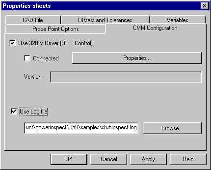
Log files are recorded by PowerINSPECT using Measures- Parameters- CMM Configuration. Tick 'Use Log File' and set the filename to a valid path (not the default).
Log files are replayed into PowerINSPECT using CMM- Simulation. The configuration must be set to a blank Generic RS232 or Stiefelmeyer.
PowerINSPECT has a point logging function which is primarily intended for diagnostic use. The point logging function allows PowerINSPECT sessions to be reproduced quickly without the part and without the hardware.
The Point file starts with a header
Each section has its own header showing what the points were used for.
e.g.
or
The other data in the file is point data. This is described in more detail at the end of this note.
Point logging is carried out as follows.
In Measures- Parameters choose the CMM Configuration tab.
Tick the 'Use Log File' and set the filename to a valid pathname other than the default. Click 'Apply' and 'OK.'
PowerINSPECT will record all of the points you take and create a log file.
It is advisable to probe the measuring sphere at the beginning ('Change Probe' and OK) because this allows other users to ensure that the probe data is correct.
When you want to stop logging you can finish by unticking the 'Use Log File.'
CMM- Simulation (Menu: CMM- , or right click on the red flash) must be set.
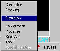
(Note- if you have no CMM configured, the following applies. The CMM Configuration (Menu: CMM- Configuration, or right click on the red flash) must be set to a blank Generic RS232 or Stiefelmeyer setting.)
Then choose a log file by browsing.
Use PowerINSPECT exactly as you would use it with a CMM connection, except that you should highlight a point line and press 'Send' rather than probing points. The number of points taken will be shown in the top right of the measuring dialog box as usual.
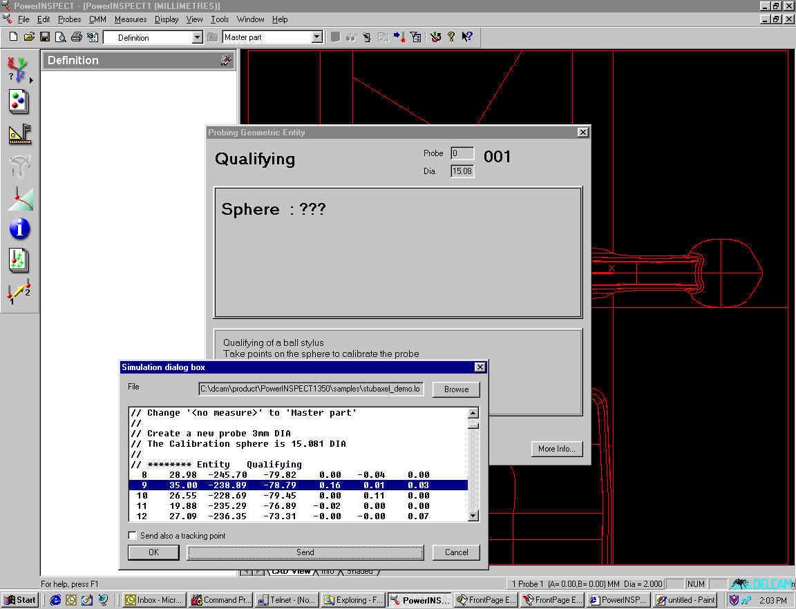
Note- You can send multiple points by selecting a number of lines and pressing 'Send.' The points will be sent in their numerical order.
In the screen shot above, from left to right the point data is composed as follows:
first number (9) = point identifier
second to fourth numbers (35.00, -238.89, -78.79) = point coordinates
fifth to seventh numbers (0.16, 0.01, 0.03) = i,j,k vector
Note that only the touch point from each pairing is shown in this dialog box.
Within the log file, the points themselves are arranged as coordinates, with a touch point and a pre-touch point in each case.
When you come to replay the points, only the touch point will appear in the dialog box.
The N and the first number indicate the number of the point (there is a touch point and a pre-touch point), and the final three numbers are the x,y,z coordinates.
The first line of each pairing is the touch point. The second is the pre-touch point. The (i,j,k) vector is calculated by subtracting one from the other (compare with the screen shot above.)
This file format works because this is the same as the Stiefelmeyer format.
A log file can be constructed using just the identifier, (x,y,z) coordinates and (i,j,k) vector if you remove the N from the identifier.