PWI000043
this document applies to :
Gripe no 389
PowerINSPECT can support a wide range of measuring machines and probe types. Rigid probes are commonly fitted to articulating arm inspection devices. This note describes measurement technique using rigid probes.
Rigid probes do not trigger automatically on contact with a surface- they are triggered by the user, usually with a button or footswitch.
When using a rigid probe you must ensure that the axis of the probe is pointing towards the material of the component while each point is being recorded. This is necessary for proper offsetting.
During guided measures the user can trigger the probe continuously. Points taken during this process will be accepted only if the probe position is sufficiently close to the intended position, within the tolerances previously defined by the user. Effectively this means that the probe is triggered automatically when it gets to an acceptable position. A progress bar at the bottom of the measurement dialog box provides useful feedback about the current probe position in guided measures.
This technical note describes measurement of 'guided' features with Rigid probes. The common characteristic of 'guided' features is that the probe must be positioned in a carefully defined area, or else points will simply not be taken. A typical example is a section. Points for section measurement can only be taken within the tolerance zone either side of a previously defined plane. If the probe is outside this area points will not be taken at all.
Rigid probes do not trigger automatically on contact with a surface- they are triggered by the user, usually with a button or footswitch. In guided measures points will be taken only if the probe is in the correct position while it is being triggered.
During guided measures you can use this to your advantage. If you trigger the probe continuously (by holding down the button or footswitch), you can move the probe within the general area of the required point, and try to pass over it exactly. Points taken during this process will be accepted only if the probe position is sufficiently close to the intended position, within the tolerances you have defined.
The effect of this technique is that the probe is triggered 'automatically' when it gets close enough to the required position. All acceptable points will be taken and all unacceptable points will be rejected.
It is important to probe the first point correctly, approaching the surface from the
direction of the surface normal.
This allows PowerINSPECT to determine the surface offset from the probe centre. This is
necessary to determine the true position of the surface. For example, when probing a
circle, PowerINSPECT needs to determine whether the surface is on the “inside”
or the “outside” of the probed circle.
If the probe is NOT nearly perpendicular to the surface for the first point, PowerINSPECT
may measure the feature incorrectly. This only applies to the first point probed in a
feature.
Shown below are examples of how to probe a plane and a sphere correctly. Each example
shows a right way and a clearly wrong way, as well as a typical ‘borderline’
case which might cause problems. You should always be sure to probe the first point
correctly.
![]()
Rigid probes are also supported with a 'Proximity Graph' which shows a larger reading as
the probe gets nearer to the required position and this is an additional visual aid.
This section describes how to measure a guided point, but the same technique applies to sections.
Guided points are used when a surface measurement is required at a pre-defined location. The aim here is to put the probe in a specified position on a surface and take a point. Guided points are described in the User Guide under 'Using Guided Points' in the 'Inspecting Surfaces' chapter.
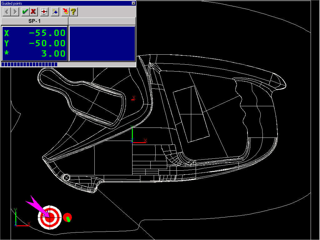
When you take points you can monitor your progress in two ways, using tracking and also using a progress bar at the bottom of the Guided Points dialog box.
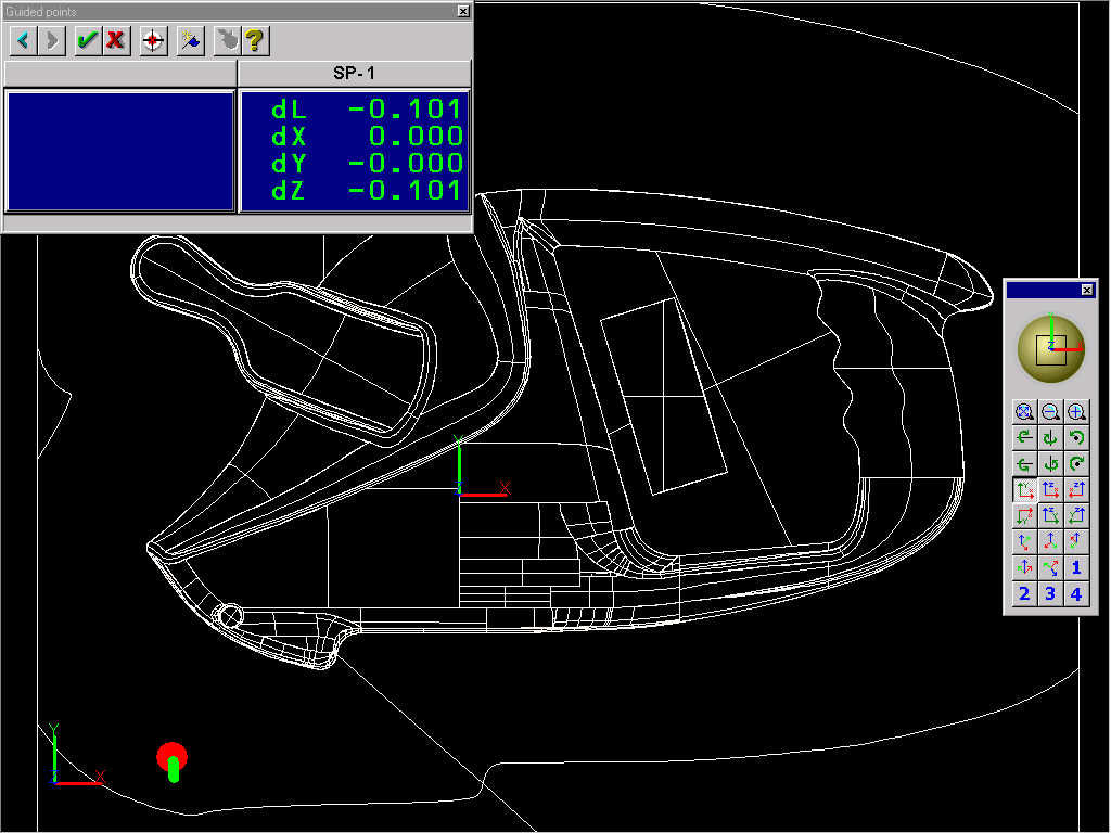
If tracking is supported on your system, you will see a representation of the probe on the screen- the aim here is to put the probe contact point on the surface of the model at the centre of the target.
You can use the progress bar by triggering the device continuously using a button or a footswitch on or connected to the measuring device. If you do this, as you move the probe across the general area of the guided point, you can see how close you are to the point using the progress bar. This blue bar at the bottom of the Guided Points dialog box gets bigger as you get closer to the target point. When you are at the target position, the bar will fill the bottom area. (This may also be accompanied by a sound from the device, depending on the type of measuring machine being used. If this is the case, the pitch of the sound will usually rise as you get closer to the target point.)
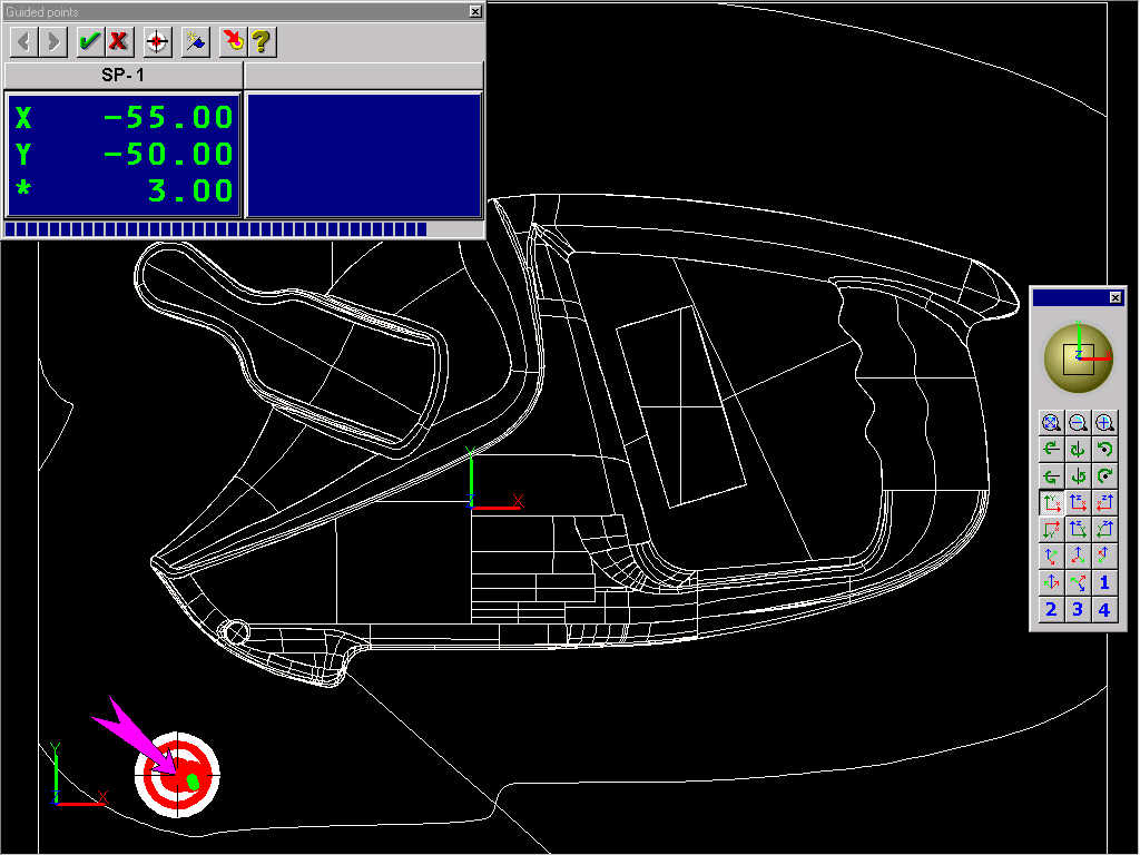
If you compare this picture with the one above, the probe is closer to the target and the bar at the bottom of the dialog box is longer.
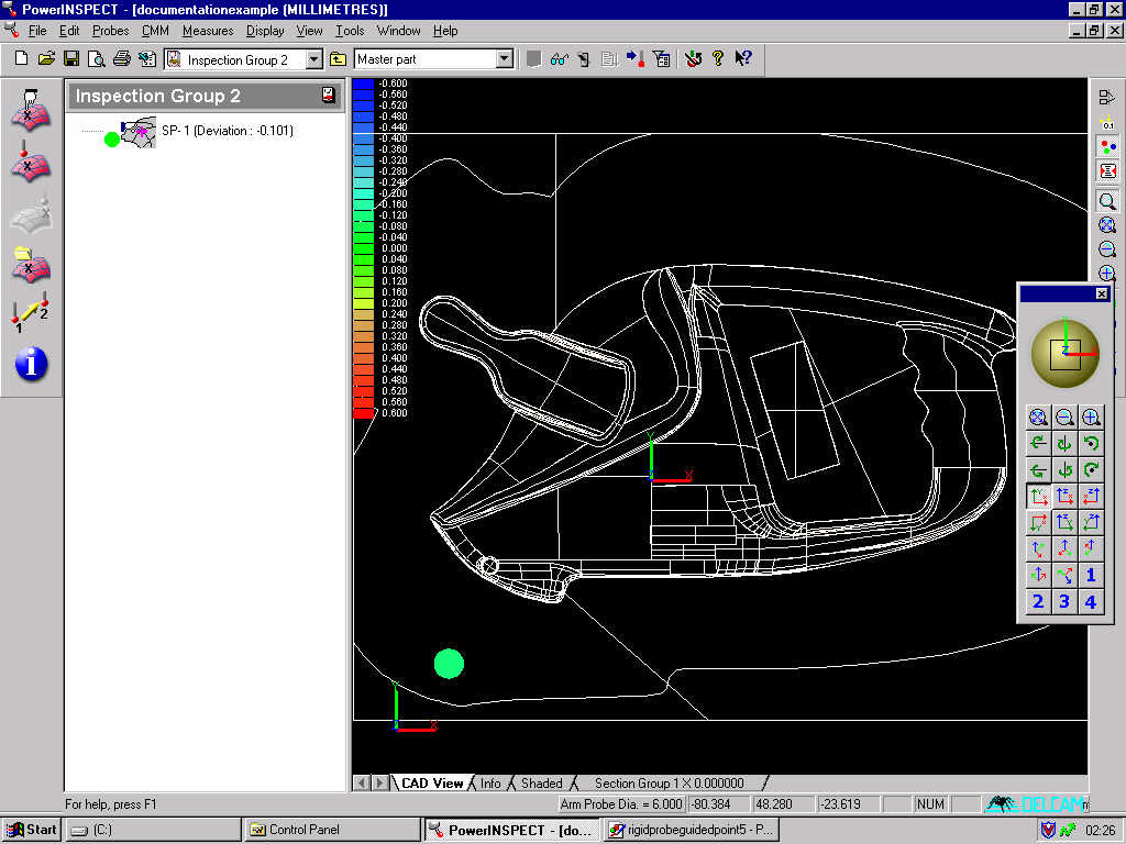
When you put the probe in the centre of the target while triggering the probe, the point will be taken. The target disappears, and measurement results appear in the right hand side of the dialog box. If you are taking a number of points, the next target will appear at this stage.
When you have finished taking points, click on the 'tick' button to finish measuring, and the points and results will be shown in the CAD view.
An edge point is at the end of a surface, where it is not bordered by another surface. There are two steps when taking an edge point:
1 Define where you want to take the edge point.
2 Take the edge point itself by placing the probe on the edge of the component such that the probe centre lies within a tolerance zone either side of the surface plane, and triggering the probe.
Edge points can only be measured at the edge of the CAD. This is the transition between CAD and no CAD- it is not simply the line between two surfaces. Edge points are normally used on pressings and other 'flat' models.
Firstly, you must create an Edge Points inspection group. This is a surface inspection group with the Edge points option checked. You can only take edge points on the fly: you cannot create a 'guided edge point'. This process described in the User Guide under 'Inspecting Surface Edges on the Fly,' in the 'Inspecting Surfaces' chapter.
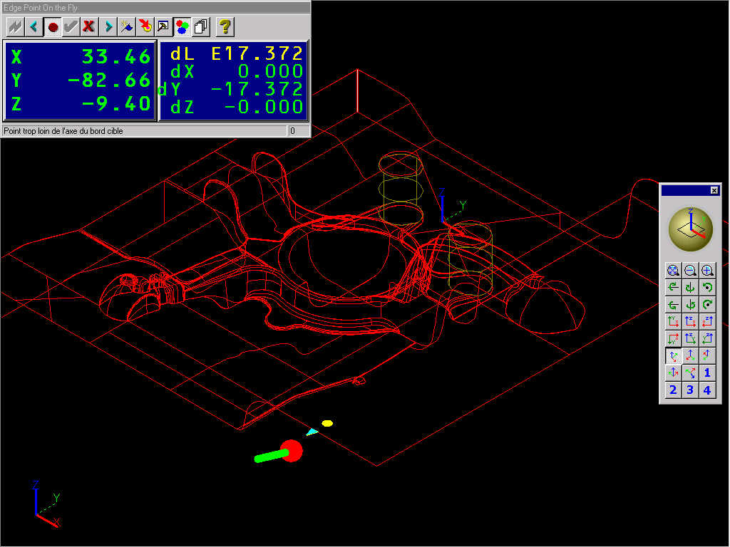
Defining where you want to take the edge point: you must first identify the surface and the approximate position where you wish to measure the edge. Place the probe on the surface a couple of mm from the edge point you wish to take. Register this location by triggering the probe with the button or footswitch. You will see a circle at the point where you probed, and a triangle at the edge point you are about to measure.
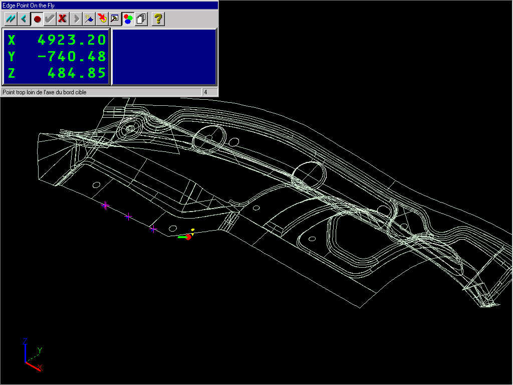
Approach the edge point to be taken from below or above the surface. Trigger the probe by pressing the button or footswitch.
Move the probe across the area of the edge point while triggering it. A point will be taken when the probe is triggered in the right place - when it crosses the edge in the specified position. The measurement data will appear in the right hand side of the dialog box.
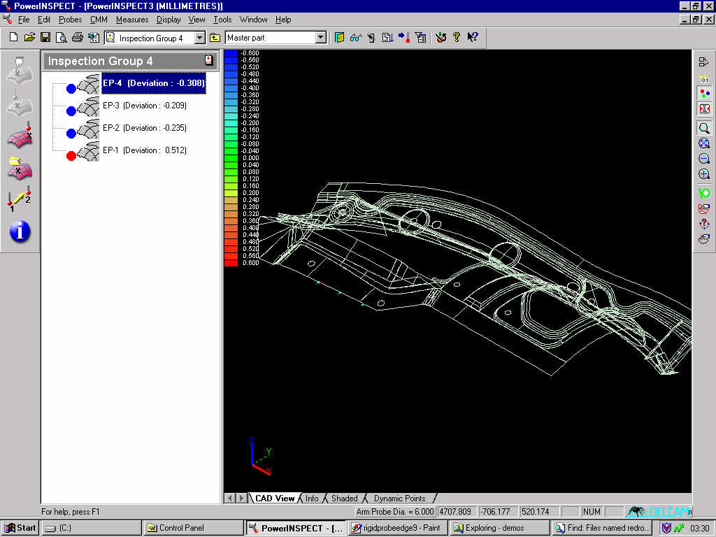
Accept the point by clicking the 'Accept' button as shown below. Probe further points as required. When you are finished, press the 'tick' - the 'Accept' button.
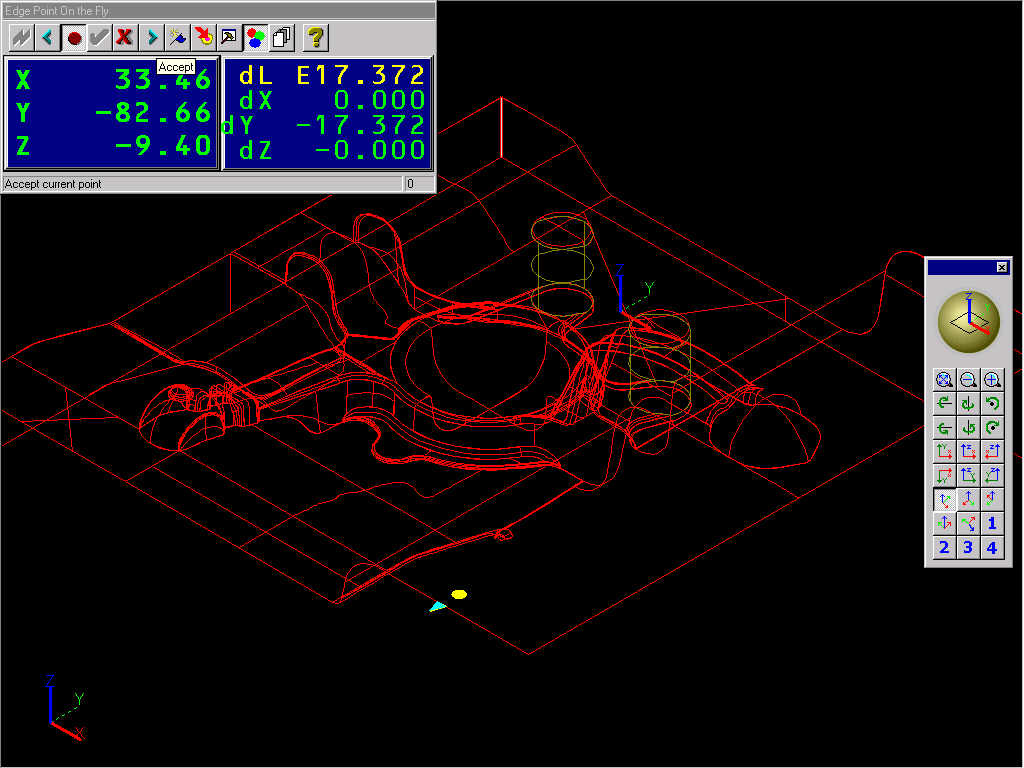
When you have finished measuring the edge points, click on the 'tick' - the 'Accept' button- after the final point. You will have a completed Edge inspection group as shown below.
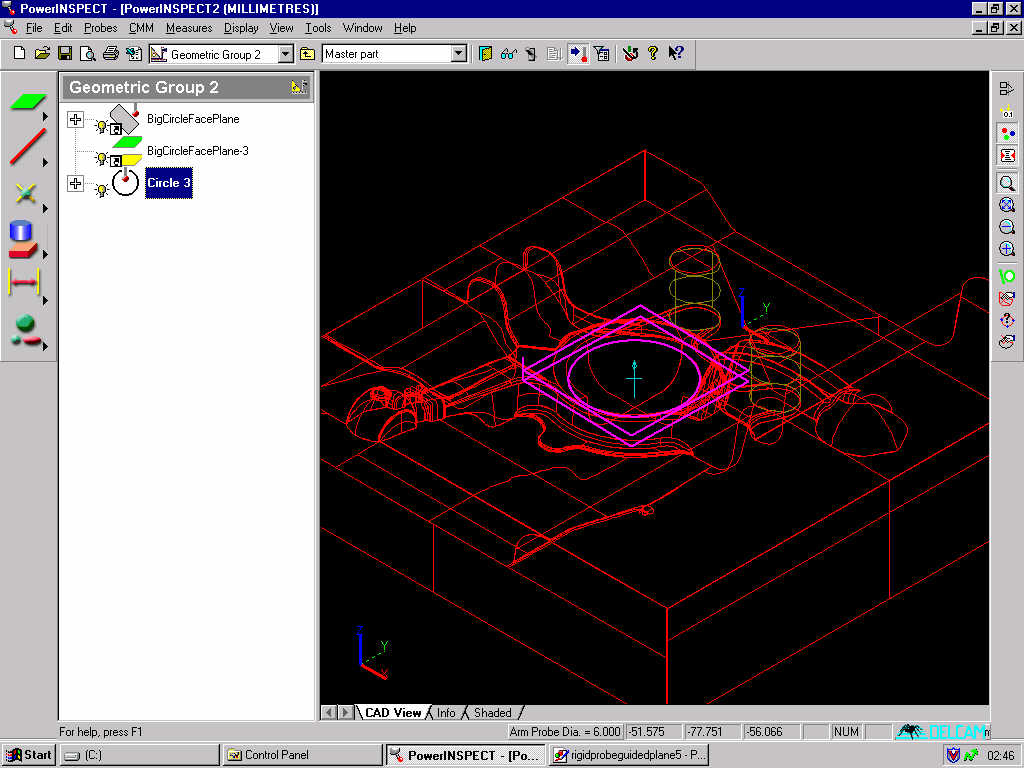
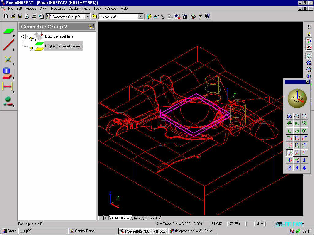
A guided plane measure is used to ensure that 2D geometric entities are accurately measured, with all points lying in a previously defined plane. In this example we will be measuring a circle around the central concave feature in the stub axle part. This feature is almost a hemisphere, so it would otherwise be difficult to ensure that the points taken were truly on a circle.
First we have created the plane which will be used for this measurement. It is a parallel plane, offset from a surface probed around the top of the central feature.
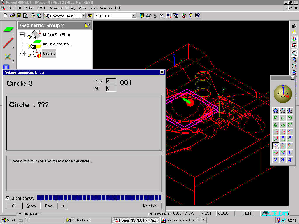
Select the circle measurement, and tick the 'Guided Measure' box. This ensures that all points taken must lie within the tolerance of the plane defining the 2D entity.
Put the probe on the model at the approximate position and trigger the probe with the button or footswitch. The 'proximity bar' at the bottom of the measuring dialog box is a guide to your progress- as you get closer to the required plane, the bar gets bigger.
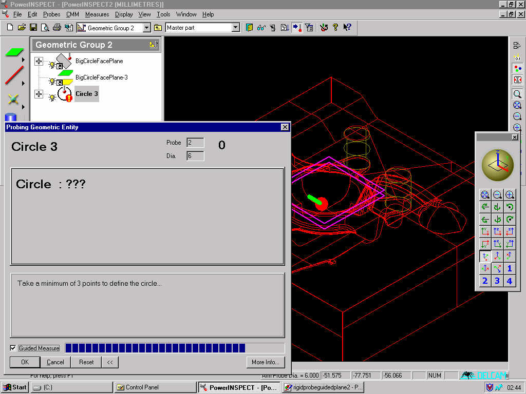
The bar at the bottom will fill the whole box when you are at an acceptable position for taking a point. If you keep the button continuously triggered (by holding down the button or footswitch) then in effect the probe will take a point automatically as soon as you pass the probe over the desired position.
When you take a point the coordinates will be displayed in the dialog box, as shown below.
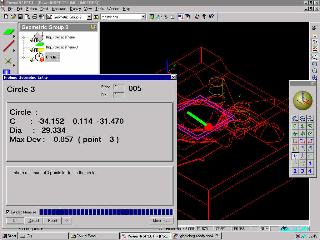
Continue to take further points as above until the geometric feature has been measured to your satisfaction. When you have finished, click on 'OK' in the measuring dialog box. The geometric feature will be displayed on the CAD as in the picture below.