PWI000044
this document applies to :
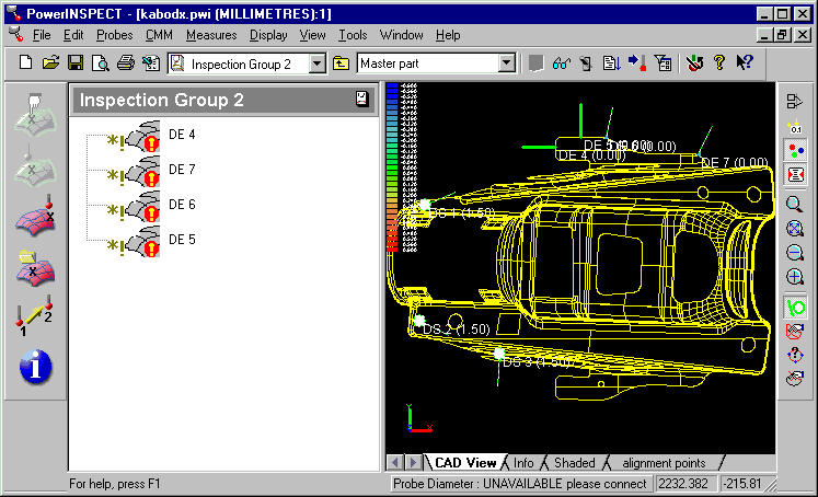
It is not currently possible to import a file of guided edge points in PowerINSPECT, but you can create guided edge points using Dynamic Points/target points. Place the Dynamic points on the model, swith Surface/Edge, move the points to the desired position, select and copy the points, and paste them in a Surface Inspection group where you have selected Edge Points and Create guided points.
Create Dynamic points using the Dynamic Points editor.
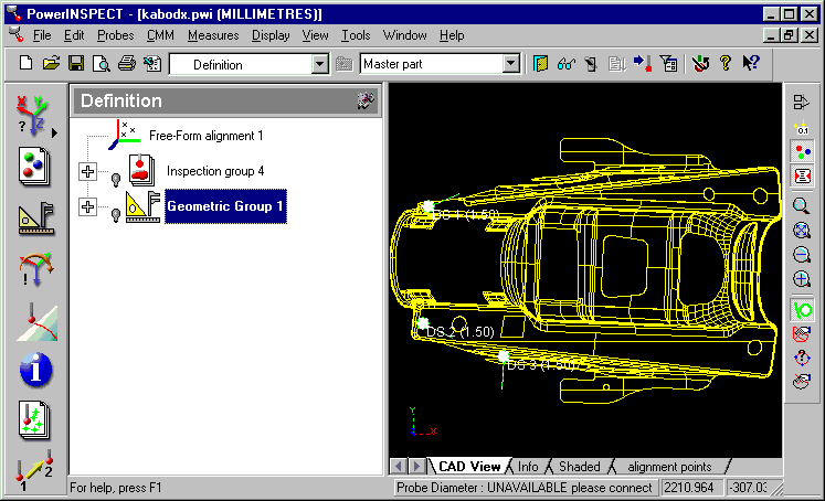
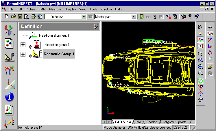
Often you will have some Dynamic Points which have already been used to create the alignment. The diagram below shows existing dynamic surface points which were used to for a free form alignment.

Place Dynamic points on the model at or near the positions you require.
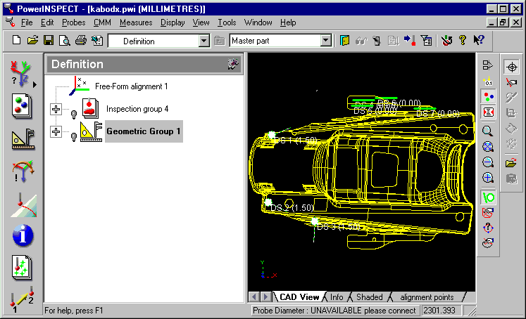
Drag the points if necessary for fine adjustment of their position. You must first select each point using the Select Dynamic Points button- then you can move it to the required position.
Note- a useful tip is to create a new window using Window- New Window. This allows you to view the Dynamic Points tab and the CAD view both at the same time.
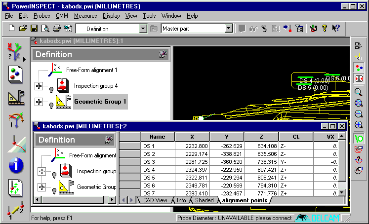
When you are happy with the position of the Dynamic Points, select each point in turn and use the switch Surface/Edge button. This will cause each of the points to become an edge point rather than a surface point. You will notice two things:
1 The normal will change position, reflecting the fact that this is now an edge point
2 The point naming will change, for example from DE 7 to DS 7, reflecting the change from Surface Point to Edge Point.
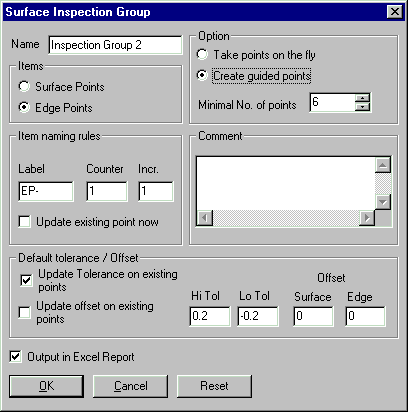
Next you should create a new surface inspection group. There are two options you must set:
1 Edge Points
2 Create guided points
You will then be asked whether you wish to probe any points on the fly. If you only wish to create guided points, you should reply 'No' to this question.

Go back to your dynamic points. Select them and Edit- Copy (or Control- C)
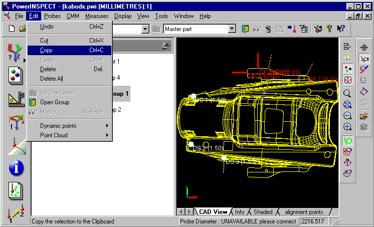
Open your new group and Edit- Paste (or Control V). This will paste the guided points into the new group.
