| Use this button to navigate to the next point | |
| Use this button to navigate to the previous point | |
| Use this button to add a new point | |
| Use this button to delete a point |
PWI000053
this document applies to :
PowerINSPECT allows you to align the part you are inspecting and the CAD data using three or more points, that have been created as auxiliary entities from geometric elements.
PowerINSPECT allows you to align the part to the CAD data using three or more points on the part for which you know the CAD co-ordinates, using a Best Fit method to match both set of coordinates.
Follow the steps below to create a Best Fit (Points) alignment:

| Use this button to navigate to the next point | |
| Use this button to navigate to the previous point | |
| Use this button to add a new point | |
| Use this button to delete a point |
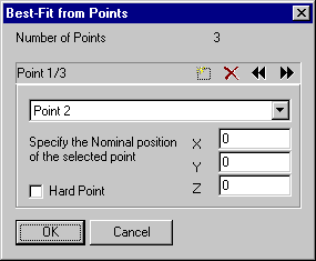
You need to enter details for at least three points, on three different pages of this dialog box. Use the arrows button to navigate through the pages, each page shows one point. On each page, you must select the point created as part of a geometric element from the drop down list box, then enter the nominals that represent this point in the XYZ boxes.
The first point can be flagged as 'Hard Point' this means that PowerINSPECT will force this point to get the specified coordinates during the calculation.
Please check the consistency of the information you provide, especially:
- All Points must be different
- All coordinates must be different.
Example :
In this example we want to set up a pressing part that has three references holes.
The three holes are defined on three different planes, and we have extracted the coordinates of the hole centres using the Wireframe checker. (The coordinates of the holes could equally have been provided by the CAD department)
Process :
- Create a geometric group by pressing this icon :
- Suspend the immediate measurement mode by pressing
on the top Toolbar, this will allow us to define the sequence elements first, and then probe the elements on request.
- Insert a probed plane , and call it Plane1
- Insert a probed Circle based on Plane1 and call it C1, we do not need to fill the nominal values here because the positioning is not yet created.
- Insert a probed plane , and call it Plane2
- Insert a probed Circle based on Plane2 and call it C3
- Insert a probed plane , and call it Plane3
- Insert a probed Circle based on Plane3 and call it C3
- Go up one level by pressing the
icon
- Then insert a 3 Point Best-Fit Positonning Item:
- Enter the details for the first point on the first page:
- Make sure that C1::Centre is selected
- Enter the nominal co-ordinates for C1::Center
- Go to the next page to enter the second point's details 2 by pressing the
button.
- Enter the details for the second point on the second page :
- Make sure that C2::Centre is selected
- Enter the nominal co-ordinates for C2::Center
- Apply the same method to enter the coordinates for the third point, C3::Centre.