PWI000059
this document applies to :
Gripe no 15
PowerINSPECT allows you to measure surfaces which are offset relative to a CAD. You may also carry out a free form fit with offset surfaces. This document explains the sign conventions. If the probe travels through the CAD surface the offset is negative. If the probe does not reach the CAD surface the offset is positive. A fuller description is given in the PowerINSPECT User Guide, Appendix B.
PowerINSPECT allows you to measure surfaces which are offset relative to a CAD. This occurs in two common cases:
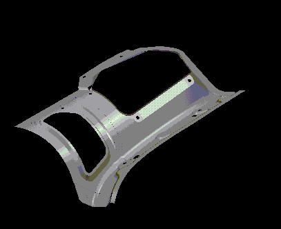
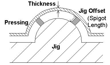
1. A CAD of zero thickness is used to represent a physical part with a small thickness that can be considered uniform. Typical examples: sheet metal pressings, fabric interior trim


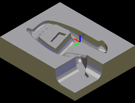
2. Electrodes: the spark gap means that the electrode is smaller than the part it will produce
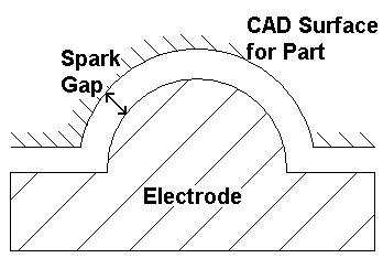
If you need to use an offset you must define its size and direction.
The sign of the offset depends on how the probe approaches the
surface. If the real surface is offset towards the probe then the offset is
positive. If the real surface is offset away from the probe then the offset is
negative. This is summarised in the diagram below.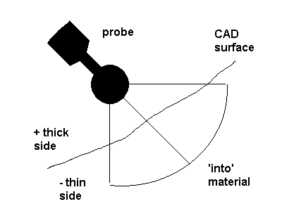
If you are using a rigid probe (commonly used on inspection arms) then you must point the probe towards the surface along the direction of travel, consistent with the diagram above.
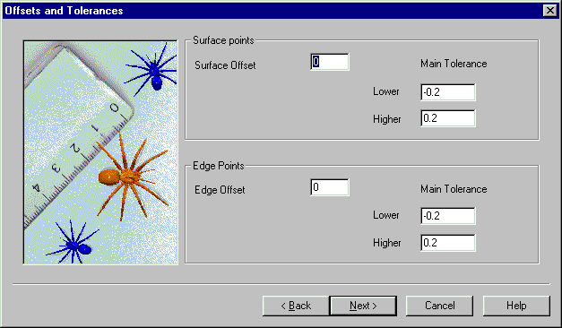
You can set the offset at the beginning of a PowerINSPECT session,
or during a session using Measures- Parameters
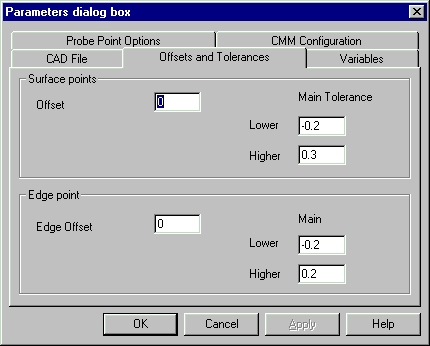
Edge points may be offset using the same convention.
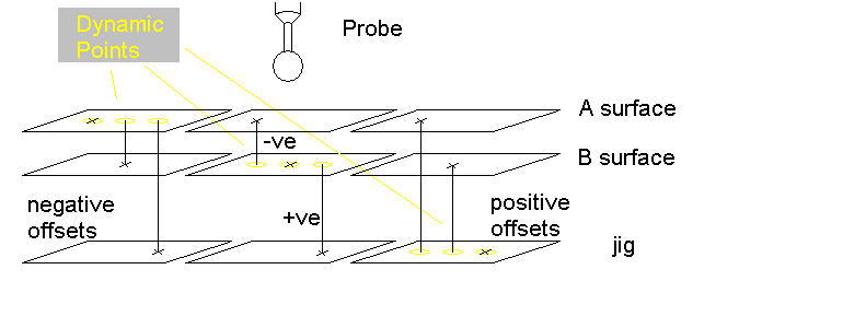
If you are using a free form fit the same rules apply. You may have to offset the dynamic points if the points you are measuring are offset relative to the CAD. The convention is the same as for the surface offset. The diagram below shows different combinations of offsets. The dynamic points are always located on the CAD surface: the X represents the point where the probe contacts the physical part.
