PWI000064
this document applies to :
Gripe no 645
PowerINSPECT has a datum feature so that you can reference geometric entities in an alternative coordinate system. The datum is created from a plane, a line and a point.
PowerINSPECT allows you to create a datum for referencing geometric entities.

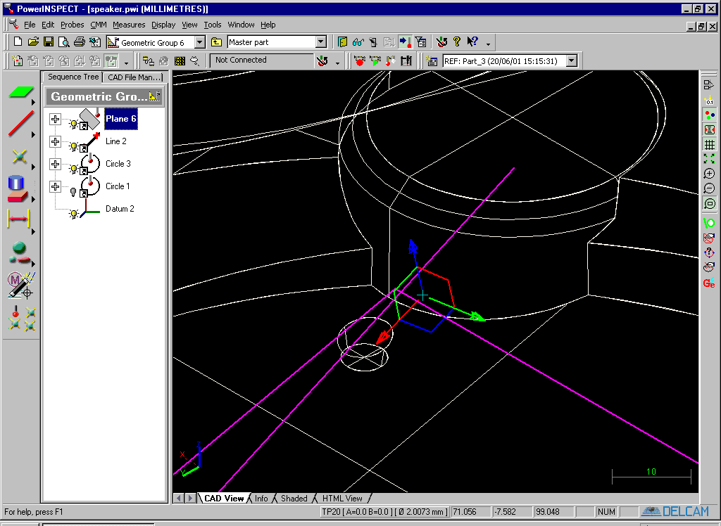
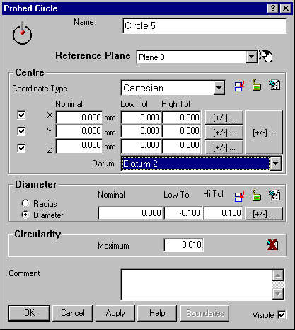
In this example, the circle centre will be reported relative to a constructed datum, Datum 2. (The default datum is the alignment). Available datums can be selected from the drop-down box, and the datum may be changed after the part has been measured (but you will need to change the nominal values if you are changing from one datum to another.)
The datum is a feature in the Geometric Entity 'Feature' ![]() list. The
datum is selected with this icon.
list. The
datum is selected with this icon.![]()
When you create the datum, you will need to add a reference plane, a reference line, and a reference point.
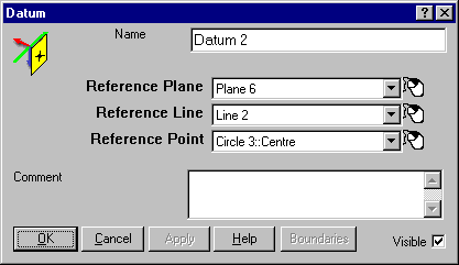
The features selected for this datum are shown below.
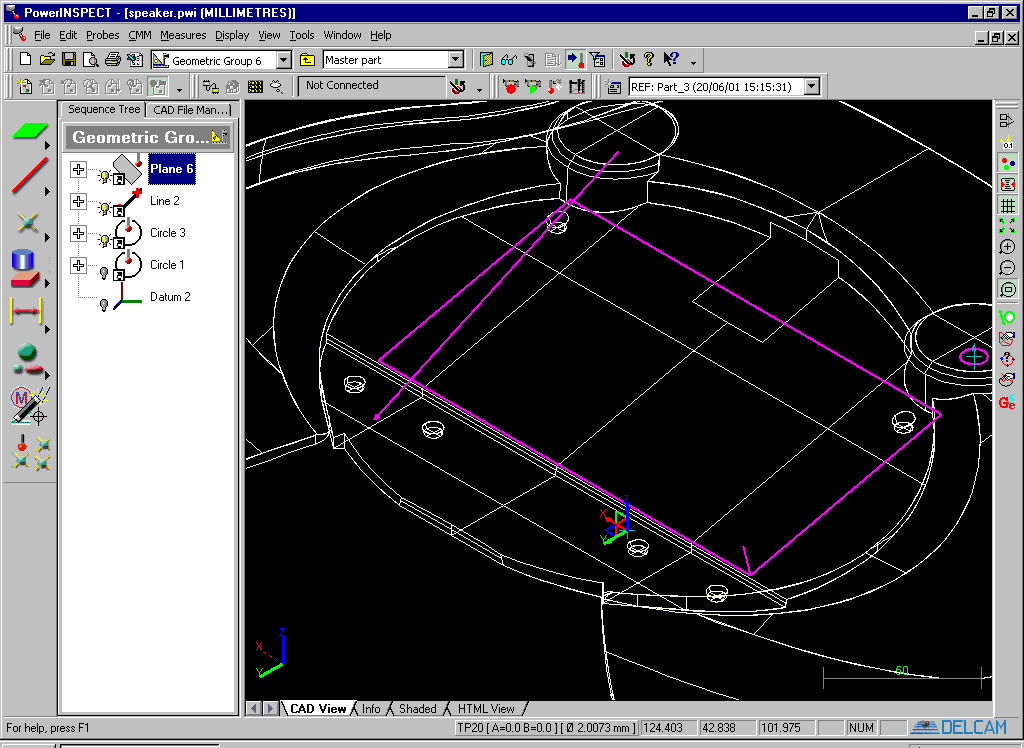
The datum is constructed as follows.
The plane is used to construct the datum plane Z=0.
The projection of the line onto the datum plane becomes the X axis for the datum. This is similar to the line projected onto a plane as shown below.
Finally the projection of the point onto this line becomes the origin. This is similar to the point projected onto a line as shown below.
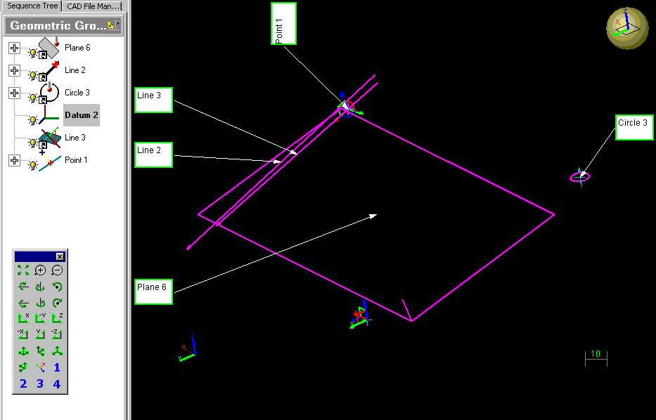
Thus the datum feature is constructed as shown below. The plane defines the Z plane and the datum origin is within this plane. The projection of the line into the plane defines the X axis, the datum origin is also within this line. The projection of the point onto this line defines the datum origin.
