PWI000072
This document applies to :
Gripe no 000
PowerINSPECT Version 2 has a 'Virtual CMM' simulator. This is a tool for developers. It can be used to explain PowerINSPECT CNC in a limited fashion.
PowerINSPECT can record points taken from a CMM in a log file. These points can then be replayed into PowerINSPECT to recreate the inspection off-line, again using the simulator. The log file contains coordinates for each point and pre-touch point. These points are grouped under headings explaining what was being measured (Surface Inspection Group, Geometric Items- Circle etc).
Log files are recorded by PowerINSPECT using Measures- Parameters- CMM Configuration. Tick 'Use Log File' and set the filename to a valid path (not the default). Log files are replayed into PowerINSPECT using CMM- Simulation. The configuration must be set to a blank Generic RS232 or Stiefelmeyer.
To use the simulator you need PowerINSPECT Version 2 as well as a version of CMMDriver 2400.
PowerINSPECT 2.0
CMMDriver 2400 or later (before CMMDriver 3)
Copy the probe database supplied and paste it into the simulator directory, giving it the name ProbeDatabase.prd. You can rename the existing .prd file, so that you can restore it later if required.
Start the simulator program (VirtualTCPCMM.exe in the PowerINSPECT directory.
Use 'Set CMM limits' on the simulator so that they exceed those on the actual CMM. ( -600 to +600 for all axes in these examples)
![]()
Enter the original probe database parameters in the simulator's
Probe Definition area. This includes the Probe Dia (2mm in this example) and the
Probe Length (72.281mm). Click Apply.![]()
Click on More... ![]() to get the other parameters. Set the
Probe Head Description values as below.
to get the other parameters. Set the
Probe Head Description values as below.
This includes the Probe Tool Mounting Point, which is the probe database head offset (-38mm in this example).
Hit OK, return to the main page and then click 'Apply' in the Probe
Definition area. ![]()
Click on the CAD button to open a window where you can view the simulation.
Load the CAD file into the simulator and use an inverse transformation matrix. First, click on the Load button and load the example file. Next, click on the Position button to display a dialog box. Click on the Charger button then load the sample matrix file. Click on the Inverser Matrice check box then on the OK button.
![]()
Open PowerINSPECT and load the example session. You can now replay the taught elements and view the process in both the CAD view and the Simulator's CAD window.
To replay log files you must access the two 'Connection flashes.'
![]()
With CMMDriver2400 the configuration must be set to 'Stiefelmeyer' and the 'Simulation' option should be ticked so that it refers to the log files.
With CMMDriver 3 the configuration must be set to 'Simulator.'
If copying from a real session, the probe offset comes from the Head 'Probe Mounting' details. You can see this by selecting the Head and View- List
The probe offset comes from the Probe 'Calib Length.' You can see this by selecting a probe position and View- List.
CMM- Simulation (Menu: CMM- , or right click on the red flash) must be set.
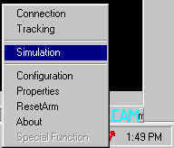
(Note- if you have no CMM configured, the following applies. The CMM Configuration (Menu: CMM- Configuration, or right click on the red flash) must be set to a blank Generic RS232 or Stiefelmeyer setting.)
Then choose a log file by browsing.
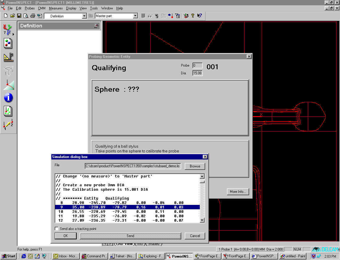
Use PowerINSPECT exactly as you would use it with a CMM connection, except that you should highlight a point line and press 'Send' rather than probing points. The number of points taken will be shown in the top right of the measuring dialog box as usual.
Note- You can send multiple points by selecting a number of lines and pressing 'Send.' The points will be sent in their numerical order.
You can calibrate the probe head on the simulator if you have an appropriate log file. Start PowerINSPECT and the simulator, open the probe database to calibrate the head, and use the simulator to send the points which need to be taken manually.
Select the first point and press the 'Send' button, and the probe calibration will receive the point.
Repeat this for the second point,
follow the directions on the Probe Calibration dialog box, and the calibration will proceed automatically.
You can watch the progress of the calibration in the CAD window.
Point logging is carried out as follows.
'Right Click' on the CMMDriver3 connection flash and select 'Start Logging.'
This brings up a browser window which allows you to specify the name of the log file.
PowerINSPECT will record all of the points you take and create a log file.
It is advisable to probe the measuring sphere at the beginning ('Change Probe' and OK) because this allows other users to ensure that the probe data is correct.
When you want to stop logging you can finish by 'right clicking' on the CMMDriver3 connection flash and choosing 'Stop Logging.'
In the screen shot above, from left to right the point data is composed as follows:
first number (9) = point identifier
second to fourth numbers (35.00, -238.89, -78.79) = point coordinates
fifth to seventh numbers (0.16, 0.01, 0.03) = i,j,k vector
Note that only the touch point from each pairing is shown in this dialog box.
Within the log file, the points themselves are arranged as coordinates, with a touch point and a pre-touch point in each case.
When you come to replay the points, only the touch point will appear in the dialog box.
The N and the first number indicate the number of the point (there is a touch point and a pre-touch point), and the final three numbers are the x,y,z coordinates.
The first line of each pairing is the touch point. The second is the pre-touch point. The (i,j,k) vector is calculated by subtracting one from the other (compare with the screen shot above.)
This file format works because this is the same as the Stiefelmeyer format.
A log file can be constructed using just the identifier, (x,y,z) coordinates and (i,j,k) vector if you remove the N from the identifier.