PWI000073
This document applies to :
This is the PowerINSPECT demonstration given at the June 2001 Technical Sales Partner Meeting. It will inspect the mobile phone used in the other PowerSOLUTION demonstrations. There are three CAD files for this demo; all are found on the TSPM2001 CD.

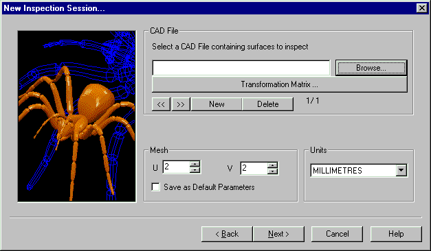
Getting the CAD: Choose the CAD from the Browser.

You can browse for the CAD according to normal Windows practice, and this will show you a list of available CAD files.
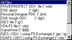
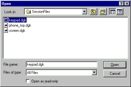
For this demonstration we are using three files to build up an assembly.


You can transform the CAD (rotation, translation etc) if required- for example if the CAD has been produced in die-line but you want to produce an inspection report in car-line. You can do this by clicking on the Transformation Matrix button.
![]()
You can then build up the transformation as necessary.
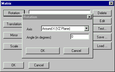
and then choose OK. In this example we have not used the transformation matrix.
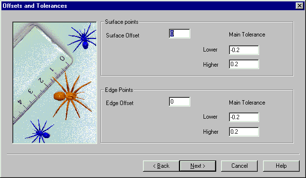
Surface or Edge points may be offset using this page: the working tolerance for the job can be entered by using the Main Tolerance facility (right mouse click) to change the tolerance band. You may set different tolerances for individual inspection groups within the session, but this defines the default settings.
Note that you can also go backwards to the previous page using the Back
button ![]() .
.
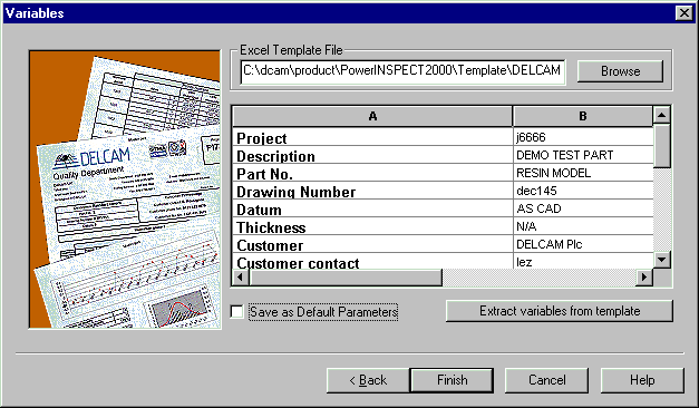
This page contains the link to the chosen Excel template and the variables specific to this inspection session.
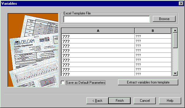
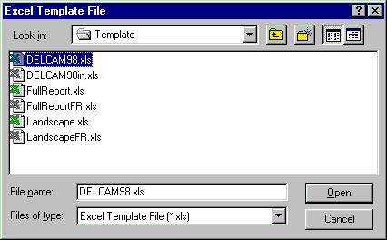
The first thing to do is choose the Excel Template file.
![]()
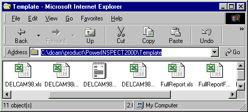
There is a templates directory associated with each version of PowerINSPECT. This contains a number of standard templates for producing reports. Normally each customer will receive a modified version of one or more of these templates to include the company logo and other customer-specific details.
The full path of the template directory is shown in the Internet Explorer window below. This is how the template directory is installed by default.
The template has default variables associated with it, which you can import into this PowerINSPECT session. This starts Excel.
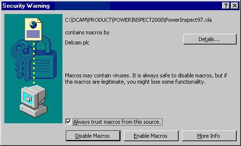
The PowerINSPECT reporting is written using macros. Due to security concerns about macros, which can carry viruses, Excel normally asks whether you want to enable macros or not. You must enable the macros in the PowerINSPECT templates to allow the reports to run.

When you complete this operation, the details from the template will be stored as part of the PowerINSPECT session. You can then edit these default values as required.

You can also choose to save these values as the default values for a new PowerINSPECT inspection, regardless of template chosen. Do this by selecting the 'Save as Default Parameters' check box.
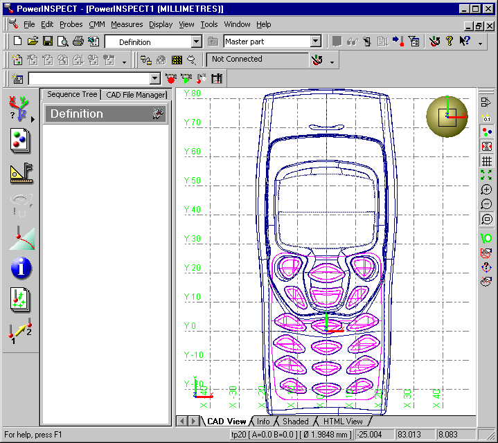
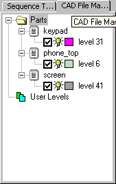
You can change the colour of the CAD wireframe, by clicking on the colour box and selecting a new colour from the palette, as shown below.
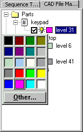
You can make a CAD level visible or invisible using the lightbulb icon. Click
on the icon to turn the level on ![]() or off
or off ![]() .
.
Similarly you can remove selected CAD levels from the inspection using the
check box. Click on the check box to include the level in the CAD context ![]() or exclude it
or exclude it ![]() .
.
Note: The Probe Database Editor is only displayed if you have a Cartesian CMM. If you are using an articulated arm or an Optical Photogrammetry system as used here in the workshops, then the dialog box displayed when you click on the Change Probe button is provided by your hardware manufacturer. For more information on how to change probes in these cases, see the manufacturerís documentation.
Many of the applications you will come across use Cartesian CMMs and the PowerINSPECT Probe Database editor, so this is briefly covered here for reference.
If a new Probe head (eg Renishaw PH10) is installed we must calibrate this first. This is outside the scope of this demonstration and is described in the What's New Guide and the User Guide. This demonstration assumes an indexable Probe Head that has already been calibrated.
This is the 'New-Look' Probe Database.
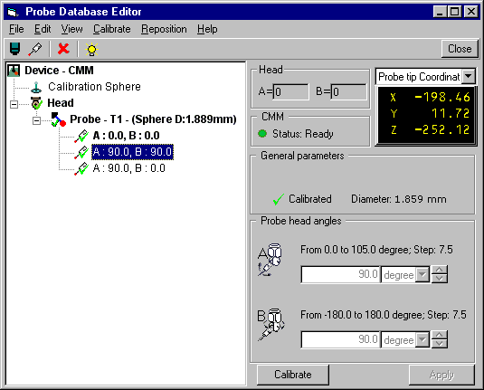
If we need to calibrate the probe but have not already done so, we must do that before carrying out any measurements. There are two stages: creating a new probe entry, and selecting and calibrating that entity.
You can calibrate the probe in one of two ways:
a) Single Position Calibration
Activate the chosen position using the Activate button. The active probe will be shown in bold type. Press the 'Calibrate' button. If using manual PowerINSPECT, follow the instructions in the dialog box.
If using CNC PowerINSPECT, PowerINSPECT automatically calibrates the probe.
As the calibration takes place, PowerINSPECT displays a progress bar and an Emergency stop button that you can press to prevent a collision if necessary. Just press 'Calibrate' to begin
b) Batch Calibration
If you want to replay this session with the VirtualCMM or the log files, you should follow the instructions in the separate documentation in the CD.
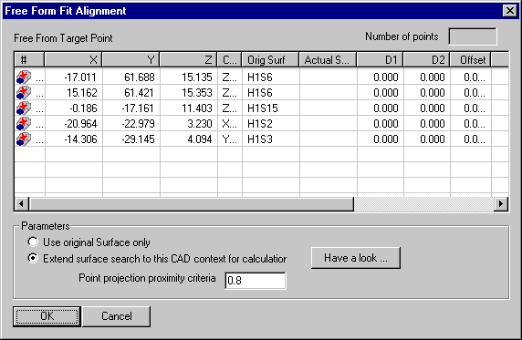
First we must create an alignment. This will allow us to relate the CAD data to physical part for inspection. We will create an alignment using a Free Form Fit. This type of alignment uses a number of target 'dynamic points' positioned on the CAD model, which are aligned to points measured on the part.
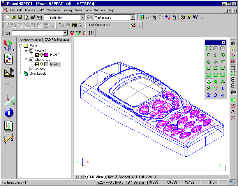
We will now position five dynamic points in the CAD View. They are selected so that the CAD is fixed in all the main axes, allowing an accurate Free Form Fit alignment.
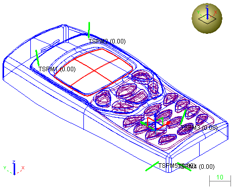
Note that you can move points into the correct position by selecting the ![]() button, then dragging the points to where you want them.
button, then dragging the points to where you want them.
Next we will take the points on the actual part that correspond to the positioned dynamic points. If you do not have access to a measuring device, you can use the simulator. This functionality is described on the TSPM 2001 CD.
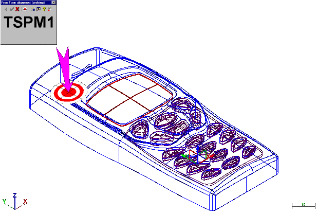
PowerINSPECT guides you to take the dynamic point using a target. Each time you take a point, the target for the next point is displayed.
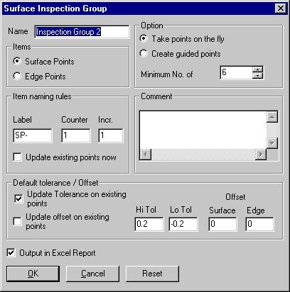
Next, it is a good idea to check the alignment and improve on it using a Best Fit item. Firstly, you must create a surface inspection group on the fly, with points on areas of the phone that need to be well-aligned. These points are then used to best fit the alignment, so that the alignment between the CAD and the part is as accurate as possible.
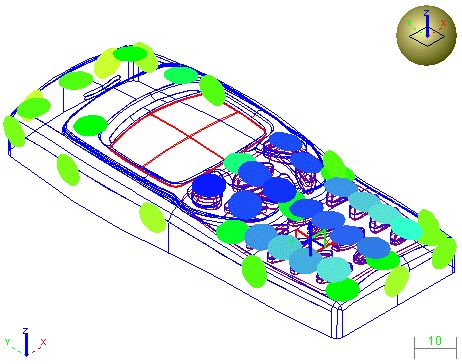
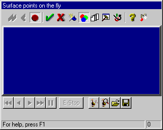
You can now use the inspection group to create the Best Fit item.
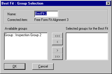
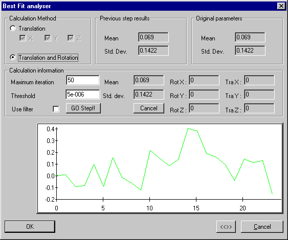
This dialog box allows you to filter out rogue points and select only to allow translation of the CAD file, rather than translation and rotation. If the points you have taken are within an acceptable tolerance (here 0.4), you can leave the default settings.
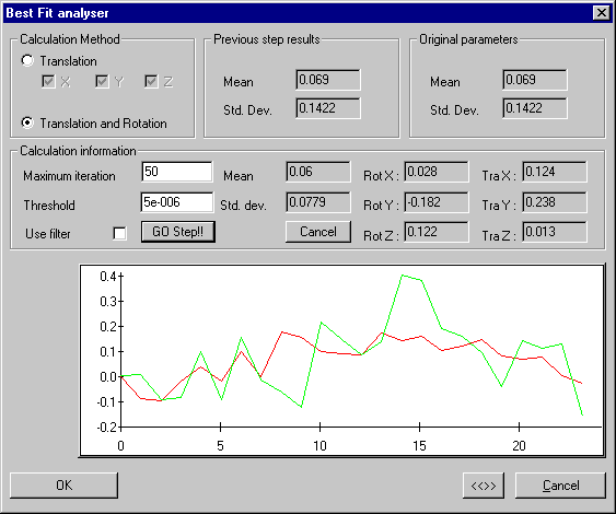
You can now carry out your inspection, knowing that you have an accurate alignment between the part and the CAD. In this demo, we will carry out a surface inspection on the fly, and a section inspection.
During the surface inspection, we will check whether the keys on the phone, which are in a separate CAD file - keypad.dgk, are accurate.
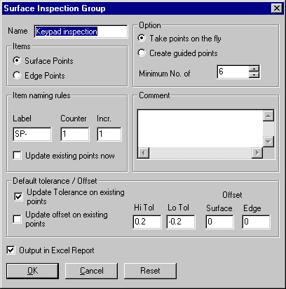

The confetti which shows the inspected points is blue. If the points had been within tolerance, the confetti would have been green. All the points in this group are out of tolerance by about - 0.3 and - 0.6. This shows that the keypad CAD is wrongly positioned in relation to the phonetop and screen CAD files.
We will now inspect a section through the phone. This will confirm that the problem is only on the phone's keypad, and not on the underlying body of the phone.
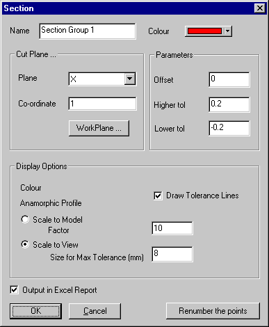
PowerINSPECT displays the CAD View full screen for you to take points. A line is shown across the part at the correct position, in the colour chosen in the 'Section' dialog box. You should take points along this line. They will be shown as confetti, using the usual surface inspection colour conventions.
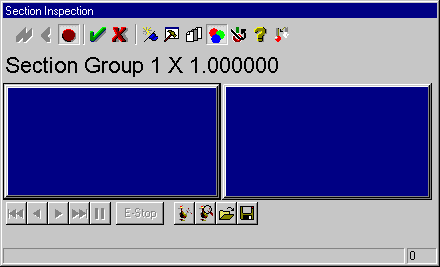
When you have finished measuring the section, click on the 'green tick' ![]() to stop measuring. The screen will revert to the normal CAD and sequence
tree view, showing the inspection confetti along the section line.
to stop measuring. The screen will revert to the normal CAD and sequence
tree view, showing the inspection confetti along the section line.

A new tab will also appear at the bottom of the screen as a result of this measurement- the 'Section Group' tab. If you click on this tab you will see the section view.