PWI000074
This document applies to :
This is the second PowerINSPECT demonstration given at the June 2001 Technical Sales Partner Meeting. It will inspect the back of a stereo, and demonstrate the use of multiple CAD files, edge points, extracting nominals from the wireframe and aligning the part using a Best Fit from Points. There are two CAD files for this demo; both are found on the TSPM2001 CD.

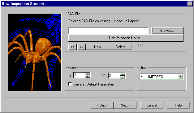
Getting the CAD: Choose the CAD from the Browser.

You can browse for the CAD according to normal Windows practice, and this will show you a list of available CAD files.
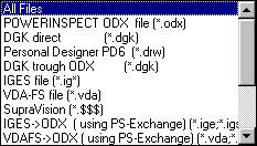
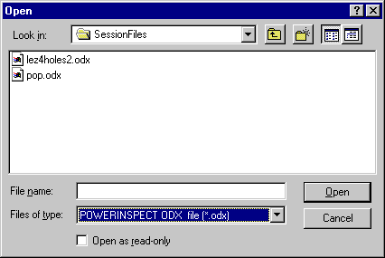
For this demonstration we are using two files to build up an assembly.


You can transform the CAD (rotation, translation etc) if required- for
example if the CAD has been produced in die-line but you want to produce an
inspection report in car-line. You can do this by clicking on the
Transformation Matrix button. ![]()
You can then build up the transformation as necessary.
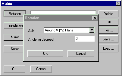
and then choose OK. In this example we have not used the transformation matrix.

Surface or Edge points may be offset using this page: the working tolerance for the job can be entered by using the Main Tolerance facility (right mouse click) to change the tolerance band. You may set different tolerances for individual inspection groups within the session, but this defines the default settings.
Note that you can also go backwards to the previous page using the Back
button ![]() .
.
This page contains the link to the chosen Excel template and the variables specific to this inspection session.
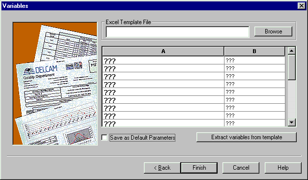
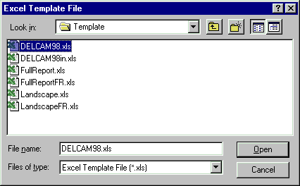
The first thing to do is choose the Excel Template file.
![]()
There is a templates directory associated with each version of PowerINSPECT. This contains a number of standard templates for producing reports. Normally each customer will receive a modified version of one or more of these templates to include the company logo and other customer-specific details.
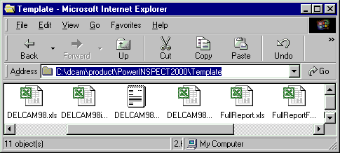
The full path of the template directory is shown in the Internet Explorer window below. This is how the template directory is installed by default.
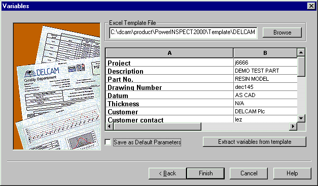
The template has default variables associated with it, which you can import into this PowerINSPECT session. This starts Excel.
The PowerINSPECT reporting is written using macros. Due to security concerns about macros, which can carry viruses, Excel normally asks whether you want to enable macros or not. You must enable the macros in the PowerINSPECT templates to allow the reports to run.
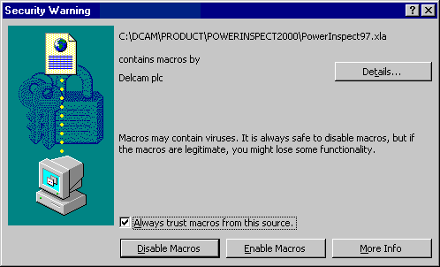
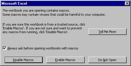
When you complete this operation, the details from the template will be stored as part of the PowerINSPECT session. You can then edit these default values as required.

You can also choose to save these values as the default values for a new PowerINSPECT inspection, regardless of template chosen. Do this by selecting the 'Save as Default Parameters' check box.
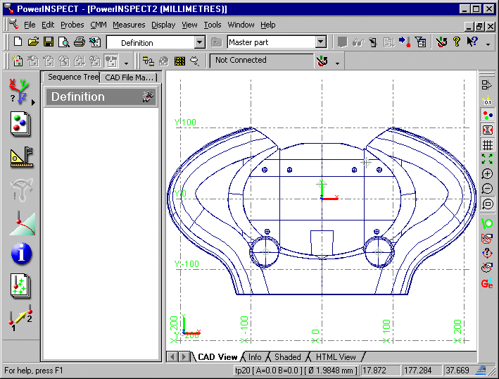
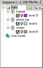
You can change the colour of the CAD wireframe, by clicking on the colour box and selecting a new colour from the palette, as shown below.
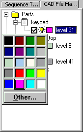
You can make a CAD level visible or invisible using the lightbulb icon. Click
on the icon to turn the level on ![]() or off
or off ![]() .
.
Similarly you can remove selected CAD levels from the inspection using the
check box. Click on the check box to include the level in the CAD context ![]() or exclude it
or exclude it ![]() .
.
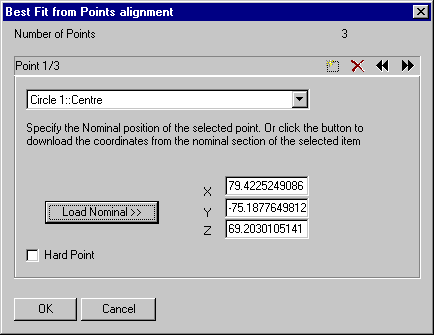
First we must create an alignment. This will allow us to relate the CAD data to physical part for inspection. We will create an alignment using a Best Fit from Points. This type of alignment aligns the CAD using already measured geometric features which represent points. The CAD nominal values for the points can be extracted from the CAD wireframe.
The first task is to create the points to use in the Best Fit from Points alignment.

We will now extract nominals from the CAD wireframe using the Geometry Explorer. We will create four circles, whose centres can be used as the points in a Best Fit from Points alignment. Each circle will need to be projected to a local plane, so we will tell the Geometry Explorer to create four Probed Plane geometric elements as well.
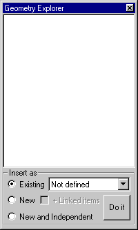
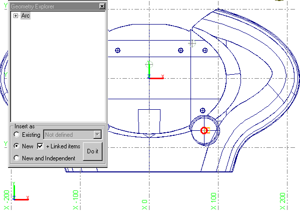
Note the new functionality in PowerINSPECT Version 2: You can now create geometric entities, with all of the appropriate nominals, directly from the CAD.
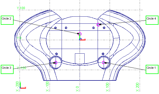
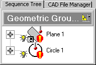
Make sure that you create the circles in the right order - you will be using them next in the Best Fit from Points alignment. When you have finished, the Sequence Tree for Geometric Group 1 should look like below.
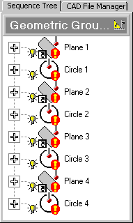
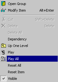
You can now play the elements and take the points on the part using your measuring device. When you take the points for each plane, make sure that the points you take are local to the circle you are measuring.
We can now create the alignment.
![]()

Next, it is a good idea to check the alignment and improve on it using a Best Fit item. Firstly, you must create a surface inspection group on the fly, with points on areas of the phone that need to be well-aligned. These points are then used to best fit the alignment, so that the alignment between the CAD and the part is as accurate as possible.

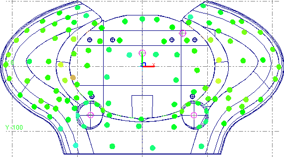
You can now use the inspection group to create the Best Fit item.
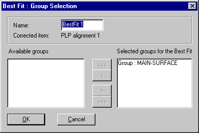
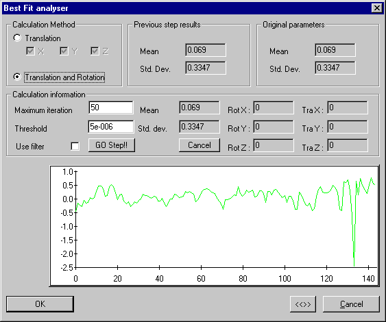
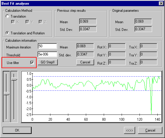
This dialog box allows you to filter out rogue points and select only to allow translation of the CAD file, rather than translation and rotation. In this example, you can see that there was a single point that deviated by 2.5. You can eliminate this point from the Best Fit using the filter.
You can now repeat the Best Fit, using points taken around the edge of the part as well
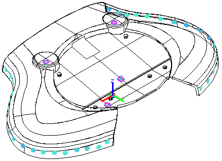
You can now use both inspection groups to further optimise the alignment.
You can view the results of the Best Fit and how it has adjusted the alignment in the Info tab.
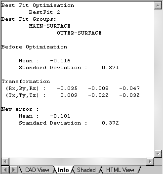
We will now inspect various geometric features on the stereo part.

You can now inspect the geometric features as shown in the example below. Work down the list in the Sequence Tree, and make sure that you change the probe after measuring Slot 2 and before measuring Plane 5.
Note: If you are carrying out this demo using a logfile, you do not need to carry out the probe change. Just play the points in the log file for the relevant geometric elements.
For the Rectangles and Slots, use "PLP Alignment 1::Plane Z(XOY)" as the reference plane. PowerINSPECT projects the each rectangle and slot to the reference plane.
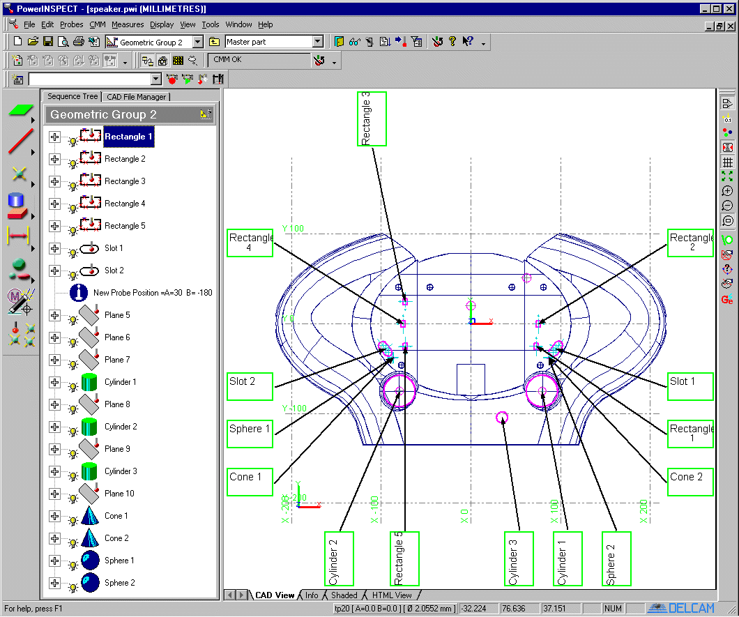
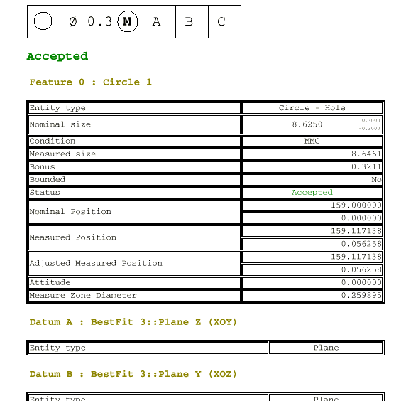
You can view the results of each geometric measurement in the HTML View, as shown in the example below.
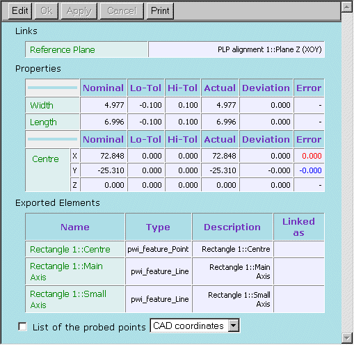
We will now inspect an edge of the stereo part. An edge is where there is no neighbouring CAD surface in a CAD file. You can inspect edges to ensure a clean fit with another part.
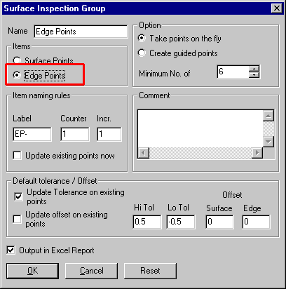
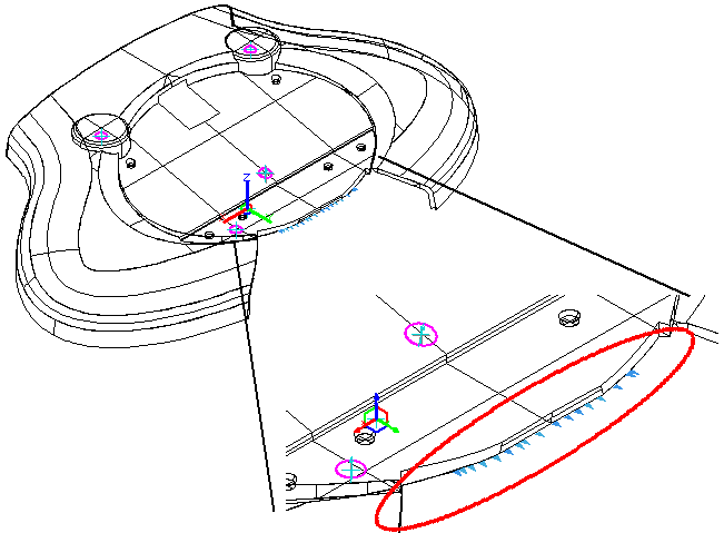
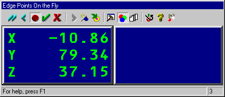
The method you use to inspect the edge depends on the type of probe you have mounted on your inspection device.
When you finish you should have results that look like this:
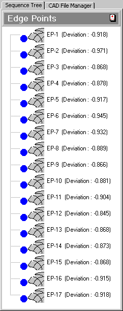
This shows that this part has edges which deviate from the CAD nominals by about -0.9mm.
GD&T is one of the most important new features in PowerINSPECT 2. The following GD&T measures have been used in this example.
Note the new functionality in PowerINSPECT Version 2: You can now measure flatness and print it to the Excel report.

Flatness is measured automatically on all planes when you measure more than three points; you can decide whether or not to include it in the Excel report.
Note the new functionality in PowerINSPECT Version 2: You can now measure flatness and print it to the Excel report.

Circularity is measured automatically on all circles when you measure more than three points; you can decide whether or not to include it in the Excel report.
Note the new functionality in PowerINSPECT Version 2: You can now measure cylindricity and print it to the Excel report

Cylindricity is measured automatically on all cylinders when you measure more than six points; you can decide whether or not to include it in the Excel report.
Note the new functionality in PowerINSPECT Version 2: You can now measure conicity and print it to the Excel report

Conicity is measured automatically on all cones when you measure more than six points; you can decide whether or not to include it in the Excel report.
Note the new functionality in PowerINSPECT Version 2: You can now create GD&T Relative Measures with the GD&T Wizard.
Note the new functionality in PowerINSPECT Version 2: You can now print detailed reports on Geometric Entities with the HTML report.
Parallelism of Cylinder 1 measured relative to Cylinder 2.
Note the new functionality in PowerINSPECT Version 2: You can now measure Parallelsim and print it to the Excel report or create a full HTML report

Perpendicularity of Plane 7 measured relative to the Z plane.
Note the new functionality in PowerINSPECT Version 2: You can now measure perpendicularity and print it to the Excel report or create a full HTML report

Co-axiality of Circle 1 and Cylinder 1
Co-axiality of Circle 3 and Cylinder 1
Note the new functionality in PowerINSPECT Version 2: You can now measure co-axiality and print it to the Excel report or create a full HTML report.

True Position of Circle 1 relative to Circle 3 (Z Plane, Y Plane)
Expected dimensions: 159, 0
Note the new functionality in PowerINSPECT Version 2: You can now measure full 3D True Position and print it to the Excel report or create a full HTML report
