Document Name: PWI000085
This document applies to :
Content
2. Requirements for connecting to Renishaw Cyclone
3. Making the Physical Connection
6. Using the Tracecut Software
A) Setting up the Cyclone in TraceCut
PowerINSPECT 2.001 Service Pack 3 and later can be used with a Renishaw Cyclone running Tracecut 24 Beta and later. The connection is via a serial line which connects PowerINSPECT to the Renishaw Cyclone software (Renishaw Tracecut). This document assumes that the Renishaw Tracecut software is already running successfully on the PC. PowerINSPECT is run as normal. The Renishaw Tracecut software outputs point data via the Remote Data Output. The Tracecut software provides single points (for geometric entities etc) using the Digitise functionality,and scans using the 3D Surface Operations.
This is a 2 PC connection. The Renishaw Cyclone has operating software (Renishaw Tracecut) running on one PC, and PowerINSPECT runs on a second PC. The two PCs are connected with a serial cable.
This guide assumes that the Renishaw Cyclone is already working with some version of Renishaw Tracecut.
1. Make sure that Renishaw Tracecut 24 Beta or later is installed on the 'Renishaw' PC (PC1). (A Renishaw dongle is required.) (link to other documentation)
2. Make sure that PowerINSPECT 2.001 SP3 or later is installed on the 'PowerINSPECT' PC (PC2). (A PowerINSPECT dongle is required.) (link to Installation Guide)
Connect the PCs with a serial cable from COM1 on the 'Renishaw' PC (PC1) to COM1 on the 'PowerINSPECT' PC (PC2).
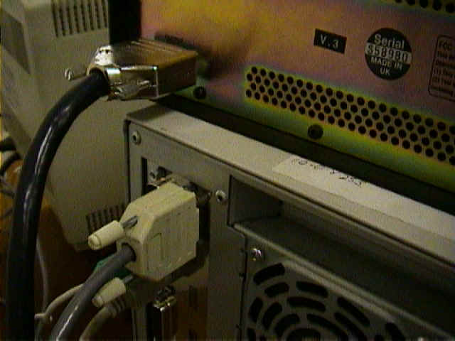 Connect to COM1 on Cyclone PC |
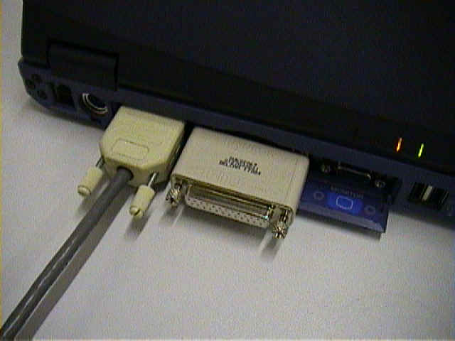 Connect to COM1 on PowerINSPECT PC |
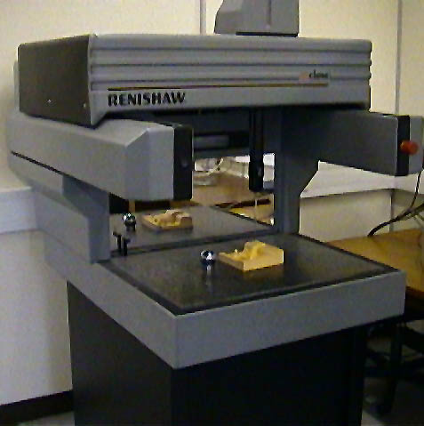
Start up the Tracecut software. A general view of the software is shown below.
In the Tracecut software you navigate between functions using the 'tree browser' in the panel on the left. Click on + to open a function. To move to another function you must first close the current function by clicking on the -.
In the Tracecut software you must set the Export Device to "Remote Data Output"
![]()
Select "Remote Data Output" to connect to PowerINSPECT.
In PowerINSPECT you must set the CMM-Configuration to Renishaw Tracecut as shown.
No Parameters need to be set for this protocol. The protocol assumes that the serial line is attached to COM1. If it is not possible to use COM1, see the troubleshooting section at the end of this document.
Press the connection icon to connect.
You will need to use three areas in the Tracecut software.
A) Seting up the Cyclone in TraceCut
i) Initialising the Machine
ii) Creating a Datum in TraceCut
B) Taking Single Points (Used in PowerINSPECT for probe calibration, geometric entities, individual surface points etc)- Digitise
C) Scanning areas (Used in PowerINSPECT to take surface points throughout a defined area)- 3D Surface Operations
D) Replaying Batch files (Used in PowerINSPECT to replay a succession of single points, e.g. to measure a geometric group)- Use TraceBatch
i) Initialising the Machine
Before a Cyclone can be used for scanning it must be Initialised. This process links the Cyclone to the TraceCut software, Calibrates the probe / stylus attached and defines the default datum (front of the machine on the right).
From main screen menu choose the option Job Datum. From the sub-menu select Initialise machine.
The following dialogue will appear.
Select OK
This will present you with a dialogue called Probe setup. In this dialogue you should enter the type of stylus you are using (ball, square, disc or star) with its nominal diameter and also the approximate length of the probe you are using.
When this dialogue is completed and OK is chosen, the Cyclone will move above its calibration position and automatically carry out measuring cycles to establish the absolute datum position of the machine and also the diameter of the chosen probe.

A number of information dialogues will appear during this 5 minute Initialisation process. They are for information only. The only time you will need to interrupt the process is if the probe fails to go to the DATUM BALL. In this instance select the REPOSITION button and manually move the probe over the top of the DATUM BALL.
At the end of this sequence a dialogue will be opened showing the measured size of the probe. You can accept this size or enter another value if you wish. For the purposes of using PowerINSPECT you should always accept the value given.
The Initialisation process is now complete.
ii) Creating a Datum in TraceCut
Even though we are going to use PowerINSPECT to align the part to our CAD model, we need to define a basic datum in TraceCut which we will use to aid single point and 3D data capture.
Creating a Z Plane
Select Set Z Plane from the Job Datum menu
Jog the probe to a position above the plane and select OK in TraceCut. Once the Cycllone has captured the point the 'Set Z Plane' Dialogue will re-appear.
Take a further 2 points on the desired plane in the same way. Note: Where possible use a plane which is parallel to the bed of the Cyclone.
After the third pints has been taken the following dialogue will appear
Select OK to make the Z plane you define = 0
Axis Alignment
Select Axis Alignment from the Job Datum menu.
Jog the probe to a position on the part where there is a straight edge (when possible this should be done across the front face of the part). Set the Direction variable to match the search direction you wish the probe to move. (X = across front of machine, Y= front to back of machine). Select OK to capture first point.
Take a second point in the same way
Once the second point has been taken TraceCut will go back to the Job Datum menu.
Creating a Datum in X & Y
Select Datum Edge from the Job Datum menu
Jog the probe to a point near the edge to be X=0
Select X+ (or X-) in the Direction pull down menu.
Select OK to move the probe onto the surface

Select OK to create the X datum position
Repeat the Datum Edge process for the Y Plane
Note: You can also use a boss, Sphere or bore to create teh X & Y Datums. If you wish to do this please refer to the TraceCut help file.
This is to take single points in PowerINSPECT. This is required for probe calibration, alignment, geometric entities and any other time when you need to control which points are taken. When you take these points they are recorded into a batch file which can be replayed later.
Select OK and this will activate the following dialogue box
To take a point, move the probe by hand (jog) to the required position above the part, choose the direction you want the probe to move (in the Cyclone machine axes) and press ok.
 |
JOG MODE?
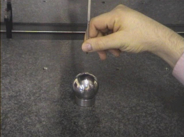
Moving the probe by hand is referred to as 'Jog' mode. To Jog the probe always hold the probes stilii and move the probe slowly to the desired location |
The probe will move in the specified direction until it makes contact with a surface. It will then retract to its original position, and a point will be received in PowerINSPECT. Repeat as required.
To calibrate the probe in PowerINSPECT you must carry out the probe calibration within PowerINSPECT, and use the Digitise (single points) function in Tracecut to provide the calibration data.
When you open the probe database in PowerINSPECT it will initially be empty.
![]()
To calibrate the probe you should define it as a fixed probe (Renishaw TP1 is suggested) and follow the probe head calibration instructions. Note- the calibration sphere on a Renishaw Cyclone is generally 50mm.
When you are asked to probe points on the calibration sphere you should carry this out using the Digitise option in Tracecut.
Once you have collected approximately 5 points on the sphere, press OK in the PowerINSPECT software to create the new calibration file for the Cyclone's probe.
The most familiar usage of a Cyclone is to scan a defined area. This is useful with PowerINSPECT to carry out surface inspection (similar to PowerINSPECT CNC pecking on a CNC CMM). This allows the user to define an area which is to be inspected, and the measuring device carries out the inspection without further input from the user.
The first step is to use the 3D Surface Operations. Select 3D Surface Operations, Capture and Create.

This is how you define the overall area to be scanned.
a) The Chordal Tolerance must be set to a high value (e.g. 20). TraceCut uses the chordal tolerance to remove points as it scans (primarily for Reverse Engineering applications). The default value is very low (eg 0.01mm) so you will need to change the value each time you create a new 3D Scan
b) The rapid height defines the distance above the model which is considered 'safe' i.e. the height at which the probe can be moved without any chance of collision.
c) The directory and filename describe the file in which the scanning parameters are saved. This allows the same scan to be replayed in future.
Other than the above 3 items leave the rest of the options as default.
To add a scanning grid select Add from the menu.
Select the 'Jog' button to define the area to be scanned.
Jog the probe to the bottom left corner of the required scanning area and press Select. Jog the probe to the top right corner of the required scanning area and press Select. This has now created a square boundary for scanning. Press OK to accept.
Within the Add dialogue, there are a number of variables which need to be set.
1. Set the Z minimum to be lower than the lowest point on the part to be scanned
2. Set the Z Maximim to be higher that the highest point on the part.
3. Click in the 'Grid Type' option and select which type of grid you wish to use. TraceCut allows you to use X & Y parallel scanning strategies, angular scanning strategies or radial scanning strategies.
FYI : X scans run accross the front of the machine and Y scans run from front to back.
4. Set the pitch and step over distance to a sensible figure. We recommend that you should set both to approximately 5mm.
5. Set the scanning speed to 6000
Leave all of the other options.
Select OK to finish.
In PowerINSPECT setup an Inspection Group and then select the Points On The Fly icon. This will prepare PowerINSPECT for receiving points from TraceCut through the serial connection.
In TraceCut select the Receive option to start the scanning, and follow the instructions.
 |
The scanning process in TraceCut NOTE: As well as streaming points into PowerINSPECT. The finished scan is a *.mod file which CopyCAD can read directly. |
You can save a batch file which consists of a sequence of single points. This allows you to record a sequence of 'single point' measurements. This gives you a type of 'teach and learn' which is useful for replaying sequences such as a free form fit alignment, or a Geometric Group.
When you have just finished measuring a sequence of single points in Tracecut you can save the sequence by exiting completely from the Tracecut software.
You can then replay the sequence using Tracecut Batch.
1. Exit all running versions of TraceCut
2. Double click on the TraceCut Batch 24 Icon
3. Select Add File from the TraceCut Batch Dialogue
4. Find the Batch file (*.bch) you need
5. Highlight the file and select Run. This will activate TraceCut and run the Batch File selected. This is very useful for rerunning the alignment sequence. Note You must watch TraceCut rerun the sequence of single points and press OK (in PowerINSPECT) when the Cyclone has finished capturing points for each specific element.
Cannot Use COM1.
If it is not possible to use COM1, you must change the appropriate line in the Renishaw Tracecut generic script. (dcam\product\PowerINSPECT2001\Drivers\RenishawTracecut.gsc)
Solution
' Open the serial port
blnConnected = Comm.Open( "COM1", 19200, 7, EVENPARITY,
RS232_XONXOFF )
______________________________________________________________________________________
Points Missing in PowerINSPECT
When the Cyclone scans over the corner of a part PowerINSPECT will have trouble finding the appropriate surface to measure to. When PowerINSPECT fails to find a surface the point is not projected but is held within PowerINSPECT as a 'probe centre point' (raw data). This 'raw' point will be used in the best fit process and if many exist in a scan it will effect the best fit process
Solution
If a scan is to be used for a Best Fit process in PowerINSPECT make sure that the scan (or set of scans ) is taken in an area where there are no sharp corners in the CAD model.
_______________________________________________________________________________________
TraceCut Software shows an Error
The Probe Power Supply Unit will buffer any points which cannot be processed by the TraceCut / PowerINSPECT link. If points are being read into PowerINSPECT too quickly, then the Probe Power Supply Unit's buffer may become full. When this happens TraceCut will lock up and display an error.
Solution
To solve this kill TraceCut and then switch off the Probe Power Supply (switch at rear) for 20 seconds. You will then need to activate TraceCut and repeat the Initialisation procedure.