
Although the installation procedure will vary depending on the application software, and the operating system (2000, XP), it is basically a matter of:
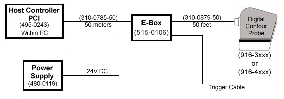
The connection of the components (showing part numbers and maximum cable lengths) are displayed in the following schematic:
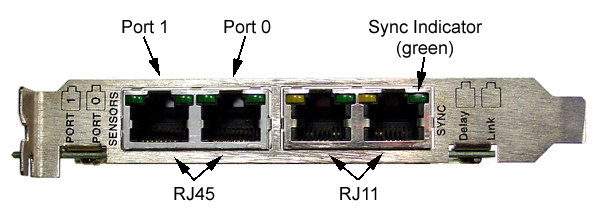
The PCI Host Controller is a circuit board which plugs into a vacant Peripheral Component Interconnect (PCI) slot of a personal computer. It is fully compliant with PCI specification 2.1, and has plug-and-play capabilities. Any PCI slot should work, however, it is recommended that slots designed to be shared with an ISA card be avoided.

The board has two RJ45 connectors (Port 0 & 1). The board also has two RJ11 connectors which provide synchronization capability with other external circuitry. Diagnostic indicator LEDs are provided and are viewable from outside the PC.
Shutdown the host computer and install the Host Controller card. Plug one end of the ColdLink cable (310-0785-XX) into "Port 0" on the PCI card and the other end into the "HOST COMM." port on the font of the E-Box.
IMPORTANT NOTE - Do not attempt to use a standard ethernet cable in place of Perceptron's cable. The electrical properties of an ethernet cable are different and using it my damage the Contour Probe and/or the E-Box.

Plug one end of the sensor cable (310-0879-XX) into the Digital Contour Probe, and the other end into the "SENSOR COMM." port on the back of the E-Box. Following your vendor's instructions plug the trigger cable into the "TRIGGER" port on the E-Box.

Lastly, plug the power connector into the "INPUT POWER" connector on the E-Box and power up the E-Box. Correct power wiring can be verified by the +12 VDC, -5 VDC, and +5 VDC LEDs illuminating. Correct sensor wiring can be verified by the illuminated +5 VDC, and +12 VDC LEDs on the Contour Probe. The "SENSOR COMM. IN", and "SENSOR COMM. OUT" LEDs on the E-Box should also be dimly illuminated. You may now proceed to the software installation.
IMPORTANT NOTE - Do not attempt to connect or disconnect cables or sensors while the E-Box is powered on. Always turn power off before making hardware changes.
If your application has not already installed the Contour Probe software (check their installation instructions), you must install it yourself. The installation process is simple. Using the application install CD-ROM, locate the file:
setup.exe
Double clicking on the file (or selecting Add/Remove in the Control Panel) will start the installation process.
After accepting the License Agreement and entering your name and company name, the setup utility will ask you to choose the ContourProbe type.
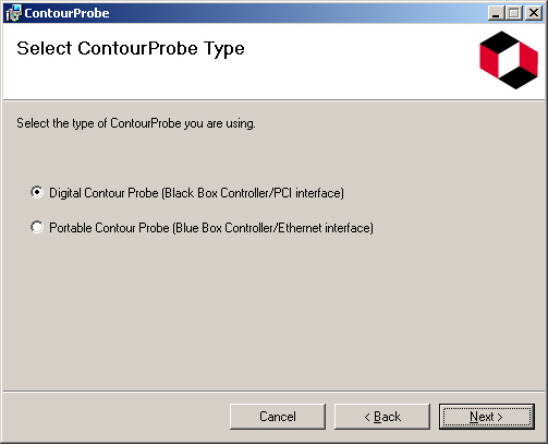
Select "Digital ContourProbe" and click on Next.
You are now prompted to choose a destination location for the software.

The default location is:
C:\Program Files\Perceptron\ContourProbe
Check your application installation instructions. They may ask for a different destination. If you wish to limit access to your user ID, select the "Just me" button. Choosing "Everyone" makes the software and utilities availiable to all logon accounts.
Clicking on "Next" will take you to the Confirm Installation dialog box.

Clicking on "Next" will begin the software installation. If the process completes successfully, you are presented with the Installation Complete dialog box.

You are now ready to load and start the ColdLink driver.
In order to access the ColdLink card, it's driver must be installed and started. After the PCI card has been installed and the system booted, the Plug and Play facility will present you with the following dialog:
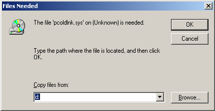
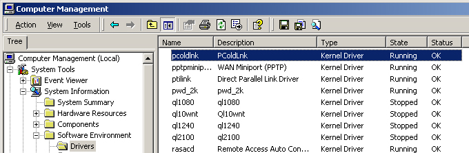
The driver file is pcoldlnk.sys, and resides on the root directory of the CD. Simply set the drive identifier to the CD and click on OK. To check that the PColdLink driver is running, from the Start menu:
Scroll down to the pcoldlnk entry and verify that Started = True and the State = Running, and Status = OK .
In order to access the ColdLink card, it's driver must be installed and started. After the PCI card has been installed and the system booted, the Plug and Play facility will present you with the following dialog:
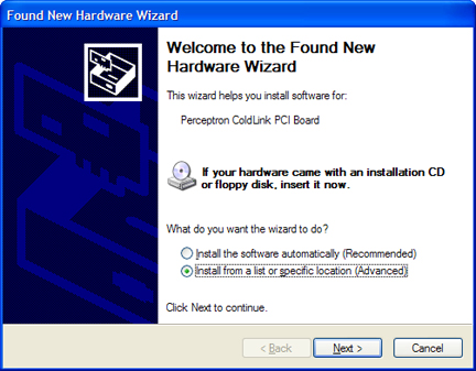
Select the "Install from a list or specific location" radio button. When prompted to choose the search and installation options, select the "Search removable media" check box. Make sure your installation CD-ROM is in the drive, and click on "Next".
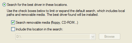
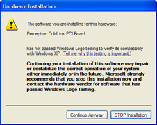
You will be presented with a dialog box that states the Perceptron ColdLink PCI Board has not passed Windows Logo testing. Click on "Continue Anyway".
To check that the PColdLink driver is running, from the Start menu:
Start -> Settings -> Control Panel ->
Administrative Tools -> Computer Management -> Device Manager
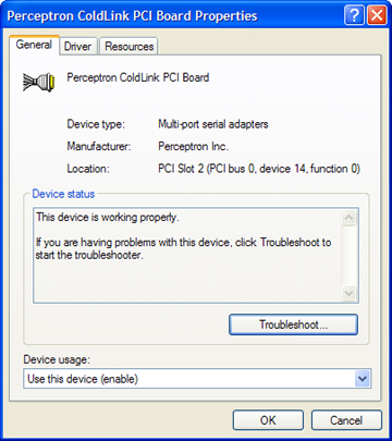
From the device list, select
Multi-port serial adapters -> Perceptron ColdLink PCI Board
From the resulting Board Properties dialog box, you should see the message "This device is working properly."
Perceptron's Contour Probe is designed to gauge the distance to objects in its field of view. To accomplish this, the sensor uses:
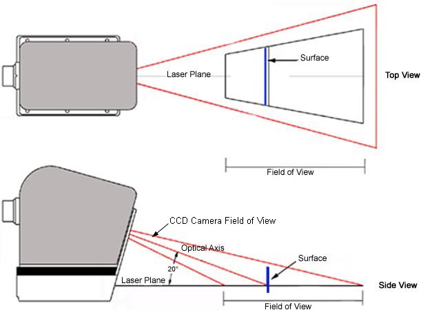
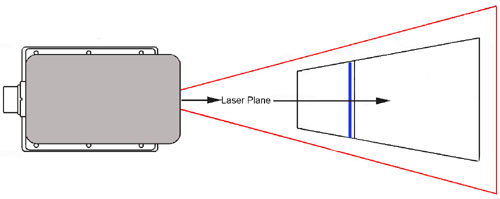
The laser projector conditions a laser beam into a plane of uniform intensity across the width of the CCD's field of view. When the plane strikes a target, it appears as a line in the CCD camera. The camera focuses on an area of that plane centered about 100mm from the face of the sensor. The optical axis of the camera is set at a 20-degree angle with the laser plane.
Triangulation is the process of using simple geometry of triangles to compute a distance. By knowing two angles and the leg between them, the other elements of the triangle can be computed. In particular, a target in the laser plane close to the camera appears on the lower portion of the CCD, and a target in the laser plane further from the camera appears on the higher part of the CCD. Once the sensor is calibrated with a process known as rectification, triangulation allows the range to all objects in the field of view to be gauged very accurately by the sensor.
The sensor is composed of optical, electronic, and mechanical components which work together with sophisticated software to generate quality 3D data at high speeds.
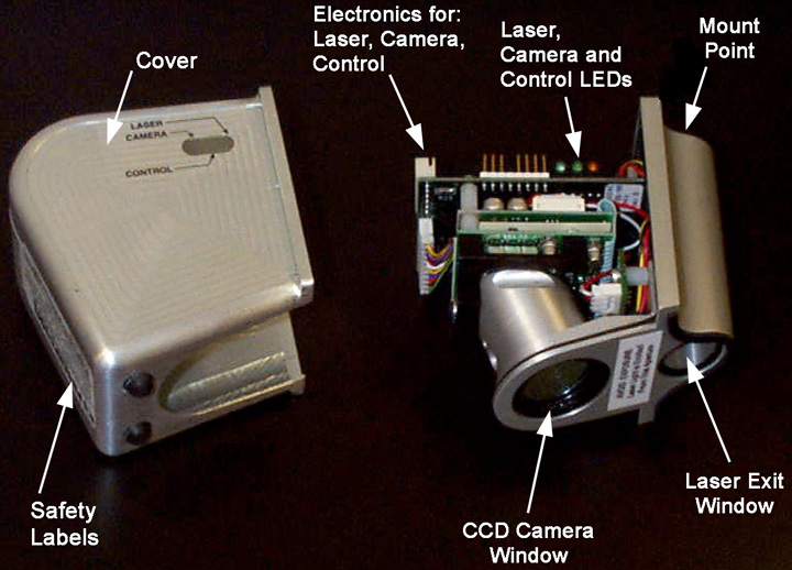
The mechanical package is designed to be light weight and solid in order to maintain its dimensional tolerances. The mechanical package provides protection from electrical noise while permitting cable access through either a connector, or, in some configurations, through wires or contacts available through the physical mount. Several physical mounts are available, each designed to provide a solid, repeatable locator for the sensor. This is critical for providing correct data from the sensor. The mechanical package houses the electronics, the laser projector cell, and the CCD camera cell. The laser and CCD are held in very careful alignment to preserve the dimensional integrity of the data generated. If required, detailed dimensions are available on the drawing, Perceptron part number 009-0385.
IMPORTANT NOTE - The laser diode and its beam shaping optics are sealed within the sensor's case. Access to these parts by the user is not intended in any way. Please contact a Perceptron representative for any internal sensor service.
IMPORTANT NOTE - The Contour Probe is a precision measurement instrument. It must be handled with care at all times. It is designed to be rugged and can be used effectively on the factory floor, but, like all precision measuring instruments, vibrations and shocks must be avoided. Do not drop.
While the method of triangulation is simple, in actuality, the process of converting a laser line image into precise range data is mathematically complex, too complex to be carried out by the electronics within the sensor. For this reason, an additional component is required: the E-Box.

The E-Box uses Perceptron's proprietary ColdLink interface which necessitates a PCI interface card in the host.
IMPORTANT NOTE - The E-Box and Digital Contour Probe are a matched set (i.e. identical serial numbers) and must be used together.
The following are common questions and issues which arise during the installation process.
IMPORTANT NOTE - The laser diode and its beam shaping optics are sealed within the sensor's case. Access to these parts by the user is not intended in any way. Please contact a Perceptron representative for any internal sensor service.
IMPORTANT NOTE - The Contour Probe is a precision measurement instrument. It must be handled with care at all times. It is designed to be rugged and can be used effectively on the factory floor, but, like all precision measuring instruments, vibrations and shocks must be avoided. Do not drop.
It is recommended that all people who use, maintain, or install laser products be aware of all potential hazards. For this reason, the precautions included in this guide should be strictly observed. Use of controls or adjustments, or performance of procedures other than those specified herein, may result in hazardous laser light exposure. The use of optical instruments with this product may increase eye hazard.
Perceptron's Contour Probe Visible Laser sensors comply with Title 21, U.S. Government FDA/CDRH performance standards, Chapter 1, subchapter J, Section 1040, as applicable and the CDRH Class IIm proposed standard. The Contour Probe sensor is a Class IIm laser product as defined by the CDRH proposed standard.
Our laser safety document was filed pursuant to the regulations for the administration and enforcement of the radiation control for health and safety act of 1968 (Title 21, Code of Federal Regulations, Subchapter J) and was classified as supplement 10 to accession number 8510371, which is an initial report pursuant to Section 1002.10 of the Regulations referenced above. The submittal was assigned an informal subject title of "ADDING THE Contour Probe SENSOR, WHICH IS A REDESIGNED DATACAM."
The Contour Probe has the following safety label displayed on the top of the sensor:
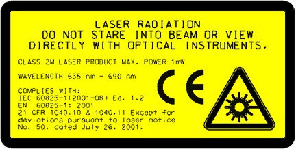
All Contour Probe sensors when properly used emit laser light at or below CDRH Class II (and the CDRH Class IIm proposed standard) power levels. As with all laser products, it is advisable never to look directly into the laser exit window.
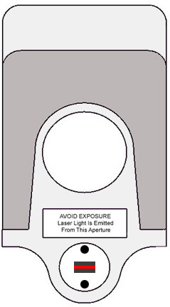
Perceptron's Contour Probe sensors contain, as their primary light source, a (InGaAIP 670 nm) laser diode. The laser diode emits a beam of red light from the laser exit window, which is visible to the human eye. In the following figure, the arrow indicates the path of the laser light as it exits the sensor.
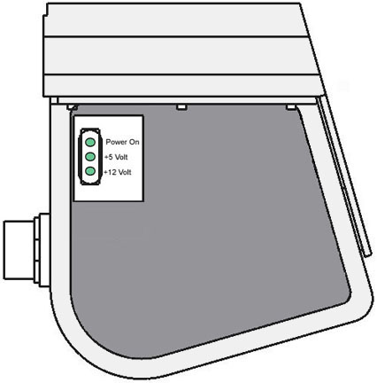
Each Contour Probe sensor has three LED indicators located on the side of the sensor. The first light signifies the Power On, while the other two display the voltage readings: +5 and +12.
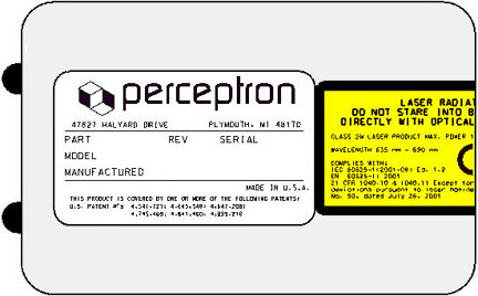
Located on the front and top of each Contour Probe sensor are warning labels regarding the laser emission and the sensor part number.
The information presented herein provides general operating instructions, engineering data and maintenance procedures for Perceptron equipment. Perceptron assumes no obligation or liability for the information presented herein or the use of the same, all such information being utilized at the recipient's own risk.
In no event shall Perceptron be liable for any direct, consequential, incidental or other damages of any kind resulting from the use of this information, including, but not limited to, loss of profits or revenues, loss of use of, or damage to, the equipment, or other property damage or injuries to persons.
The availability, presentation and conveyance of such information by Perceptron to non-Perceptron personnel does not constitute an explicit or implicit endorsement of, promotion of, or liability for such information. Except that which may be expressly provided for in service manuals or other written instructions, the recipient is cautioned against unauthorized attempts at maintenance of Perceptron equipment and related activities and that such actions could result in serious damage to such equipment, the malfunction of such equipment, injury to persons or damage to property.
In the event that unauthorized maintenance, installation, service, disassembly, adjustments and/or repairs to such equipment are conducted by anyone other than Perceptron personnel without prior written authorization from Perceptron, the warranty provided by Perceptron with respect to the equipment shall be voided, and product performance may be adversely affected.
Perceptron makes no representations or guarantees that improvements, upgrades or changes will not occur. In the interest of technical progress, the information in this manual is subject to change without notice. The examples and diagrams in this document are included solely for illustrative purposes and may vary from those which actually appear on your system.
TriCam, TriLite, VeriStar, DDM, OCF, LASAR, Wheelworks, ScanWorks, IPNet, and Perceptron are registered trademarks of Perceptron, Inc. and DataCam, Micro-Flash, Visual Fixturing, Sensing the Future, Optiflex, and InterSystems are trademarks of Perceptron, Inc.. The hardware, software, and processes described herein may be protected under one or more of the following patents: US 4541721; US 4645348; US 4647208; US 4666303; US 4745469; US 4841460; US 4862598; US 4899218; US 5006721; US 5078496, US75/728,106, EP 0543900; CA 1294427; CA 1304932; EP 280941; EP 306731; DE P3875984.5; DE P3877655.0; Case # 4226-200037 and Case # 4226-200038.
Published in the United States of America. No part of this publication may be reproduced, distributed, stored in a retrieval system, or transmitted in any form or by any means by media now known or hereafter discovered, including, and without limitation, print, electronic, mechanical, photocopying, electrocopying, recording or otherwise, as well as the right to display and transmit this work publicly on-line without prior permission from Perceptron, Inc. This documentation contains proprietary and confidential technical information. This document and the information in it are for the sole use of the customer and facility to which it has been assigned. Transfer of this material to unauthorized personnel or business entities is in violation of Perceptron's rights under the United States Copyright Act.
Perceptron
47827 Halyard Drive
Plymouth, MI 48170
Web Site:
http://www.perceptron.com
Email:
General Information: info@perceptron.com
Support: swtksupport@perceptron.com