 |
|
Noise Control in Strain
Gage Measurements
|
Electromagnetic Fields
Cabling
As with electrostatic noise
pickup, the leadwires commonly represent the principal source
of magnetic noise induction in strain gage circuits. In
intense electromagnetic fields with steep gradients (near
motors, generators, and similar equipment), ordinary
wire-twisting techniques may prove inadequate. An end view of
a conventionally twisted pair can reveal the reason for
pickup. As indicated in Fig.
501.4 , even if the induced noise were precisely equal in
both wires the amplifier noise output would be zero only if
the amplifier had infinite common-mode rejection
characteristics - an impossibility. In order to minimize
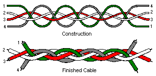
common-mode noise voltages, a special, woven, four-wire cable
has been designed which, as seen from the wire end, eliminates
the spiral inductive loops (Fig. 501.8). For maximum
cancellation of electrostatic fields, pairs of wires (composed
of one wire from each plane) are connected in parallel.
Referring to the figure, wires 1 and 2 are paralleled to form
one conductor; and wires 3 and 4 to form the other. So
connected, this type of cable is largely insensitive to
magnetic field gradients, both parallel and perpendicular to
the cable length. The cable is known as Inter-8 Weave, and is
available from: Magnetic Shield Division, Perfection Mica, 740
Thomas Drive, Bensensville, Illinois 60106.
 Fig. 501.8 - Woven cable to
reduce severe electromagnetic radiation and pickup. Fig. 501.8 - Woven cable to
reduce severe electromagnetic radiation and pickup.
Even though the strain gage is much less frequently
the significant medium for magnetic noise induction than the
leadwires, different gage patterns have differing
sensitivities to noise pickup. For instance, if the gage has
both solder tabs at one end, the net noise pickup is less than
for a gage with one tab at each end. As shown in Fig.
501.5 , the difference in noise sensitivity results from
the relative size of the inductive loop area in each case. It
is also worth noting that smaller gages, with more closely
spaced grid lines, are intrinsically quieter than large gages.
H-Series
NoninductiveGages
In severe magnetic fields,
especially those with steep gradients in field intensity,
additional measures may be required. For this purpose,
Micro-Measurements has developed a special gage configuration,
the H-Series
, consisting of two identical grids, with one stacked directly
above, and insulated from, the other. By connecting the upper
and lower gage elements in series so that the current flows in
opposite directions through the two grids, the noise induced
in the assembly tends to be self-cancelling. This arrangement
is particularly effective against magnetic field gradients and
their components parallel to the test surface. The
dual-element gage is intended to function as one arm of a
Wheatstone bridge circuit; and the bridge is usually completed
with another gage of the same type, or with a fixed precision
resistor. Standard practices are followed when installing the
gages; but the Micro-Measurements M-Bond
600/610 adhesive system is recommended for bonding, since
this will result in the thinnest glue line, and placement of
the grids as close as possible to the specimen surface.
Available from Micro-Measurements are two types of
dual-element, noninductive stacked gages - linear H06A-AC1-125-700
and a three-gage rosette H06A-AD3-125-700
.
In addition to the strain gage size and pattern, the
selection of the gage grid alloy should be given careful
consideration. If the grid alloy is magnetic, it will be
subject to extraneous physical forces in a magnetic field;
and, if magnetoresistive, will undergo spurious resistance
changes. Similarly, if the alloy is magnetostrictive, the grid
will try to change length in the magnetic field. Isoelastic
alloy, for example, should not be used in magnetic fields,
since it is both strongly magnetoresistive and
magnetostrictive. Stemming from their comparative freedom from
magnetic effects, constantan
and Karma-type
alloys are usually selected for such applications. Constantan,
however, at cryogenic temperatures and in high magnetic fields
(7-70 Tesla) becomes severely magnetoresistive. The Karma-type
alloy is ordinarily preferred for cryogenic service because of
its generally superior performance in magnetic fields at very
low temperatures.
Magnetic Shielding
When necessary,
strain gages can also be shielded from electromagnetic fields
to some degree with a magnetic shielding material such as
mu-metal. Two or more layers of the shielding material may be
required to effect a noticeable improvement. Of course, even
this will be ineffective if the source of the magnetic field
is beneath the strain gage. When high-frequency fields are
encountered, be sure that the material is suitable (high
permeability) at the anticipated frequency.
| | |
 |
